Showing posts with label S1AP. Show all posts

6/06/2016

VoLTE S1 handover execution (2/3)


S1 handover preparation procedure includes the decision of S1 handover by the source eNB, allocation of network resources to establish Indirect Data Forwarding Tunnel among two eNBs and common S-GW and establishment of uplink S1 bearer from the target eNB to the S-GW. Once the S1 handover preparation procedure is completed, the MME initiates the S1 handover by sending Handover Command to the UE via the source eNB. The UE executes the handover by detaching from the source eNB and attaching to the target eNB. Meanwhile, the downlink data is forwarded to the target eNB and buffered while the UE handover is in progress. Lastly, the UE informs the target eNB of the fact that the handover has been successfully completed and thereafter, the buffered data and downlink data is forwarded the UE through the target eNB. 

Figure 1. S1 handover procedure - execution

[8] The Handover Command received from the MME is wrapped by the source eNB within the RRC Connection Reconfiguration and sent to the UE. The RRC Connection Reconfiguration is the message to perform logical, transport and physical channel configurations. In this case, it is used to send NAS signaling to the UE to reduce the latency. Upon receiving the Handover Command, the UE detaches from the source eNB and performs handover to the target eNB.

[9] The source eNB stops assigning PDCP-SNs to downlink packets and sends the eNB Status Transfer to the target eNB via MME that contains uplink and downlink PDCP-SN and HFN (Hyper Frame Number) for each respective E-RAB. This procedure is initiated by the source eNB at the moment when it considers the transmitter/receiver status to be frozen. The use of PDCP-SN and HFN is part of overflow control mechanism for radio. The PDCP-SN is the serial number of PDCP packets increasing up to MAX-PDCN-SN. If the number reaches the MAX-PDCP-SN, the HFN is incremented by one. 
  • Subject to Transfer Items: contains uplink/downlink PDCP-SN and HFN for each respective E-RAB.
  • E-RAB ID: Identifies a radio access bearer for a particular UE. This value remains the same after S1-handover.
  • uL-/dL-Count value: contains the PDCP-SN and HFN values
  • Received Status of UL PDCP SDUs: indicates the missing and the received uplink SDUs (Service Data Units) for each bearer for which the source eNB has accepted the request from the target eNB for uplink forwarding.
  
Figure 2. eNB Status Transfer

[10] The MME forwards the received PDCP-SN and HFN information to the target eNB by sending MME Status Transfer. Upon receiving the MME Status Transfer, the target eNB does not deliver any uplink packet whose PDCP-SN is lower than the value received in the PDCP-SN in the uL-COUNT value. The target eNB uses the received PDCP-SN in the dL-COUNT value for the first downlink packet for which no PDCP-SN is assigned yet. The downlink traffic received by the source eNB is routed to the target eNB following the Indirect Data Forwarding Tunnel.

[11] After the UE successfully synchronized with the target cell, it sends a Handover Confirm to the target eNB. The Handover Confirm is contained in the RRC Connection Reconfiguration Complete message on RRC. Please note that, at this moment, there is no direct S1 bearer established yet between S-GW and the target eNB. Therefore, the downlink data is sent to the source eNB and forwarded to the target eNB following the Indirect Data Forwarding Tunnel. The uplink data from the UE will be forwarded to the S-GW following the direct S1 interface.


Red Mouse


REFERENCES

[1] 3GPP TS25.331, "Radio Resource Network (RRC); Protocol specification", v12.3.0, Sep 2014
[2] 3GPP TS23.401, “General Packet Radio Service (GPRS) enhancements for Evolved Universal Terrestrial Radio Access Network (E-UTRAN) access”, v12.4.0, Mar 2014
[3] 3GPP TS36.331, "Evolved Universal Terrestrial Radio Access (E-UTRA); Radio Resource Control (RRC); Protocol specification", v12.3.0, Sep 2009


8/04/2015

E2E VoLTE call setup(4/4) - dedicated EPS bearer creation


While SIP signaling is in progress in VoLTE call setup, a dedicated EPS bearer is created for voice media transfer. The dedicated EPS bearer for voice is temporary one as it lasts only during the voice media session which is different from the default EPS bearer in that the default EPS bearer is persistent until the UE is detached from the LTE. The creation of dedicated EPS bearer is triggered by the P-CSCF sending service data information (i.e., AAR) to the PCRF. Once the dedicated EPS bearer is created for voice, there comes two EPS bearer created between the UE and the IMS APN, i.e., a default EPS bearer for SIP signaling and a dedicated EPS bearer for voice media. On top of this, there can be more dedicated EPS bearers created with different PCC rules and QoS according to service types.


I. Introduction

The P-CSCF converts the media information in the SDP into the service data information and sends it to the PCRF. The PCRF performs session binding between IP-CAN session and the Application Session, generates PCC rules and provisions them to the SGW/PGW. The SGW/PGW requests to the MME the creation of dedicated EPS bearer using the received PCC rules. The SGW/PGW also performs bearer binding between PCC rules and the to-be-created IP-CAN bearer. The creation of dedicated EPS bearer procedure is composed of sequential procedures of creating uplink S1 bearer, DRB (Data Radio Bearer) and downlink S1 bearer across UE, eNB and SGW/PGW.

NOTE the S5 interface between SGW and PGW is not depicted in the following practice for simplicity.


II. Creation of a dedicated EPS bearer for voice traffic

The following scenario shows the procedure of creating a dedicated EPS bearer during VoLTE call setup.

Fig 1. dedicated EPS bearer creation

[59] The SGW/PGW generates its own GTP-U TEID and initiates the procedure to create a dedicated EPS bearer by sending Create Bearer Request (CBR) to the MME. The CBR contains Bearer Context information of the dedicated EPS bearer to be created.
  • (Linked) EPS Bearer ID: Indicate the default bearer associated with the PDN connection.
  • Bearer Context: a set of information for dedicated EPS bearer to be created which contains EPS Bearer ID, Bearer TFT, GTP-U TEID and Bearer QoS.
  • EPS Bearer ID : a requested EPS bearer ID to be created and shall be set to '0' at this stage.
  • Bearer TFT : the uplink packet filters to be sent all the way down to the UE and applied by the UE when the UE sends out RTP and RTCP packet.
  • SGW GTP-U TEID : the identifier of the SGW as an end point of the GTP-U tunnel.
  • Bearer QoS : QoS for this dedicated EPS bearer which includes UL/DL MBR, UL/DL GBR and QCI.

Fig 2. IEs in Create Bearer Request

[60] Upon receiving the CBR, the MME allocates the EPS bearer ID and requests the UE to activate the dedicated EPS bearer by sending Activate dedicated EPS bearer context request towards the UE. The message is delivered to the UE being contained in the E-RAB Setup request and the RRC Downlink Direct Transfer over S1AP and RRC interfaces respectively. The E-RAB Setup request contains SGW GTP-U TEID and the E-RAB level QoS parameters e.g., ARP, UL/DL MBR, UL/DL GBR, etc.
  • e-RAB ID: unique identifier of the E-RAB for the UE. Please note that the E-RAB ID=’5’ was for the default EPS Beaer with the Internet APN, ‘6’ was for default EPS bearer with the IMS APN and now, it is set to be ‘7’.
  • e-RAB level QoS Parameters: QoS to be applied to an E-RAB, which contains QCI, ARP, MBR and GBR of the E-RAB. This is a copy of the received Bearer level QoS at step #59.
  • SGW GTP-TEID: the identifier of the SGW at the end of GTP-U tunnel.
Fig 3. IEs in E-RAB Setup Request
  
The following snapshot shows the Active dedicated EPS bearer context request contained in the Non-Access-Stratum (NAS) PDU container.
  • EPS QoS: QoS of an EPS bearer context which includes QCI, MBR and GBR of the EPS bearer
  • Traffic Flow Template (TFT): the uplink packet filters to be sent all the way down to the UE and applied by the UE when it sends RTP and RTCP packet.
  • Linked Transaction Identifier (TI): the identifier of the active PDP context from which PDP address for the new PDP context could be derived.
  • Negotiatiated QoS: QoS of a PDP context
  
Fig 4. IEs in Activate dedicated EPS bearer context request

Upon receiving the E-RAB Setup request, the eNB allocates the required resources and establishes uplink S1 bearer with the SGW as part of the E-RAB establishment.

[61-62] The eNB sends the RRC Connection Reconfiguration request to the UE. The UE modifies the radio bearer accordingly and responds with the RRC Conenction Reconfiguration Complete.

[63] The eNB responds with the the E-RAB Setup response to the MME and it contains eNB GTP-U TEID which is allocated by the eNB.
  • E-RAB ID: unique identifier of the E-RAB for one UE. This value is originally assigned by the MME and if this is already occupied, the UE can change it.
  • eNB GTP-U TEID: the identifier of the eNB at the end of GTP-U tunnel. The eNB newly assigns the GTP-U TEID for this dedicated EPS bearer and it is delivered to the SGW via MME.
  
Fig 5. IEs in E-RAB Setup Response

[64] The UE responds with the Activate dedicated EPS bearer context response to the MME which is wrapped in the RRC Uplink Direct Transfer and S1AP Uplink NAS Transport on RRC and S1AP interfaces respectively.
  • E-UTRAN Cell Group Identifier (CGI): globally unique identifier of a cell (PLMN ID + ECI)
  • Tracking Area Identifier (TAI): globally unique identifier of a tracking area [PLMN ID + TAC]

Fig 6. IEs in Activate dedicated EPS bearer context response
  
[65] The MME responds to the SGW/PGW by sending Create Bearer Response. The Create Bearer Response contains the eNB GTP-U TEID which was received at step #63. Upon receiving the Create Bearer Response, the SGW establishes downlink S1 bearer towards the eNB.

Fig 7. IEs in Create Bearer Response


II. PDN connectivity and EBI allocation

The following shows the summary of all the procedures shown in the VoLTE call setup procedures, in which steps (1) to (4) are performed at the background automatically.
(1)    UE turend on.
(2)    PDN connection with the Internet APN: the QCI of the default EPS bearer = ‘9’, EBI = ‘5’.
(3)    PDN connection with the IMS APN: the QCI of the default EPS bearer = ‘5’, EBI = ‘6’.
(4)    IMS registration through the default EPS bearer with IMS APN.
(5)    The dedicated EPS bearer creation for voice upon request for VoLTE service: the QCI of the default EPS bearer = ‘1’, EBI = ‘7’.

Fig 8. PDN connection and EBI allocation


Red Mouse


REFERENCES

[1] 3GPP TS25.331, "Radio Resource Network (RRC); Protocol specification", v12.3.0, Sep 2014
[2] 3GPP TS24.301, "Non-Access-Stratum (NAS) protocol for Evolved Packet System (EPS); Stage3", v12.4.0, Mar 2014
[3] 3GPP TS24.008, "Mobile radio interface Layer 3 specification; Core network protocols; Stage3", v13.4.0, Dec 2015
[4] 3GPP TS29.274, "3GPP Evolved Packet System (EPS); Evolved General Packet Radio Service (GPRS); Tunneling Protocol for Control Plane (GTPv2-C); Stage3", v13.0.0, Dec 2014
[5] 3GPP TS36.331, "Evolved Universal Terrestrial Radio Access (E-UTRA); Radio Resource Control (RRC); Protocol specification", v12.3.0, Sep 2009
[6] 3GPP TS36.413, "Evolved Universal Terrestrial Radio Access Network (E-UTRAN); S1 Application Protocol (S1AP)", v12.3.0, Sep 2014


Last updated: 1 Jan 2016

7/16/2015

VoLTE: Traffic Flow Templates

The service data flow template is a set of packet filters applied to IP packets to identify the service data flow belonging to a specific application. The packet filters typically consist of IP 5-tuples, i.e., source IP address, destination IP address, source port, destination port, protocol type. The service data flow template is delivered to the PGW contained in the PCC rules. The PGW identifies the service data flow based on the service data flow template applied in the order of filtering priorities. Once the service data flow is identified, the corresponding QoS parameters are applied to relate the service data flow to a certain EPS bearer.

I. TFT filter
Once the bearer binding is completed, that is, the PGW builds mapping relations between EPS bearers and the corresponding PCC rules, the PGW requests the creation of the EPS bearer (i.e., Create Bearer Request) towards the MME in which the set of IP 5-tuples are interpreted as a bearer level Traffic Flow Template (TFT). The TFT can be defined either separately for uplink and downlink or for both uplink and downlink. The TFT for the downlink is used by the network element whereas the TFT for the uplink is used by the UE. The following diagram shows the TFT structure when the TFT operation is add, create or replace [TS24.008].
    • TFT operation code : the action to be taken to the TFT and/or packet filter list e.g., create, delete, add, replace, etc. 
    • Number of packet filters : the number of packet filters. In case the operation code is "Delete existing TFT" or "no operation code", the number of filters will be 0. Otherwise, the maximum number of packet filters is 15.
    • Packet filter direction: the direction of the traffic, i.e., uplink only, downlink only, bidirectional
    • Packet filter identifier: the unique number to identify the packet filter
    • Packet filter evaluation precedence: the precedence for the packet filter among all the packet filters in all TFTs associated with the PDP address.
    • Packet filter contents: variable components with variable size such as remote/local IPv4/IPv6 address, protocol identifier, remote/local port, etc.

    The following snapshot shows the TFT included in the Create Bearer Request (PGW/SGW->MME) captured over S11. The TFT operation code is to "Create a new TFT" and the direction of the IP flow to which this TFT is applied is an "uplink only" as this TFT is supposed to be used by the UE. The precedence value indicates the priority for this filter among other filters to be applied to the IP flow. Therefore this priority value must be locally unique in the UE. In this example, the IPv4 remote address indicates the P-CSCF address.


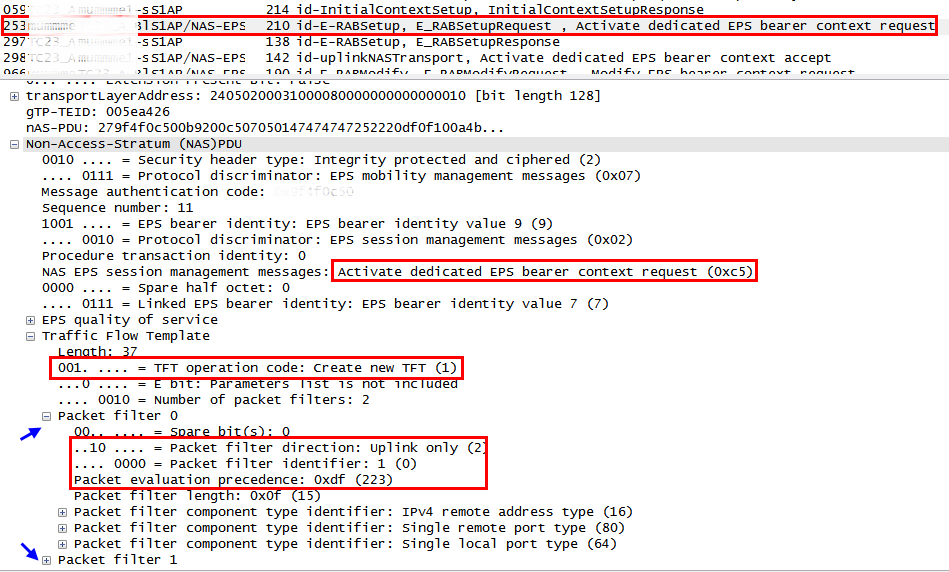
    The following snapshot shows the TFT included in the Activate dedicated EPS bearer (MME ->eNB) captured over S1AP. As the TFT is included in the NAS message, it is delivered to the UE transparently so it can be used by the UE.


    In a nutshell, the uplink-only TFT is created by the PGW based on the received PCC rules and sent to the UE so the UE can utilize it to filter and map the outgoing IP packets with the corresponding uplink EPS bearer.


    II. TFT errors
    The TFT is delivered from the MME to UE or vice versa contained in a NAS message over S1AP and the RRC interfaces. The TFT errors indicate operational inconsistencies from semantics or syntax perspectives between TFT operations, packet filters and NAS messages and once detected, it leads to the failure of EPS bearer level operations. The 3GPP TS24.301 has specified four types of TFT related errors as below:

    (1) Semantic error in the TFT operation is more likely the case when there is a contextual inconsistency in the TFT operation. The following shows example cases:
       - The TFT operation of other than "Create a new TFT" in the Activate dedicated EPS bearer context request.
       - The TFT operation of "Delete packet filters from existing TFT" when the deletion will result in the empty TFT.
    (2) Syntactical error in TFT operations is more likely the case when there is a logical inconsistency between TFT operation and the packet filters. The following shows example cases:
       - The TFT operation of "Create a new TFT" and the empty packet filter list in the TFT IE.
       - The TFT operation of "Add packet filters in existing TFT" and the empty packet filter list in the TFT IE.
       - The TFT operation of "Delete packet filters from existing TFT" when there is no corresponding packet filter in the existing TFT.
    (3) Semantic error(s) in packet filter(s) is more likely the case when a packet filter consists of conflicting packet filter component which would render the packet filter ineffective.
    (4) Syntactical error(s) in packet filters(s) is more likely the case when two or more packet filters in the resultant TFT would have component(s) with identical values such as the same packet filter identifiers, the same packet filter precedence values, etc.

    Each of the above error cause can appear in the following NAS messages as an ESM cause:

    (1) The Activate dedicated EPS bearer context reject (UE-->MME) as a failure to create the dedicated EPS bearer.
    (2) The Modify EPS bearer context reject (UE-->MME) as a failure to modify the dedicated EPS bearer.
    (3) The Bearer Resource Allocation reject (MME-->UE) as a failure to initiate the activation of the dedicated EPS bearer.
    (4) The Bearer Resource Modification reject (MME-->UE) as a failure to initiate the update of the dedicated EPS bearer.


    III. Case study
    The following snapshot has been captured while testing the conference call scenario. Having been sorted out based on the MME-UE-S1AP-ID, it shows the lifetime of the EPS bearer from when it is created until it is released due to the "semantic error in the TFT operation". In the meantime, there are five times of EPS bearer modifications occurred.

    NOTE The MME-UE-S1AP-ID is assigned by the MME to identify the UE over S1AP. In the same way, the eNB also identifies the UE by assigning the ENB-UE-S1AP-ID.


    The following snapshot shows the TFT in the Activate dedicated EPS bearer context request. Please note that there are two packet filters, one for the RTP and the other one for the RTCP. The TFT operation has to be "Create a new TFT". The packet filter identifiers are 1 and 2 and the precedence values are 223 and 191, respectively.

    NOTE the detail of the second packet filter is not shown in this snapshot.


    The following snapshot shows the TFT in the first Modify EPS bearer context request. The TFT operation is "Add packet filters to existing TFT". The packet filter identifiers are 3 and 4 and the packet precedence values are 247 and 239, respectively.

    NOTE the detail of the second packet filter is not shown in this snapshot.


    All the history of packet filters for the rest of operations can also be analyzed following the same way. The following table shows the resulting analysis of the details for all the packet filters during the lifetime of the EPS bearer.


    In this example, the last TFT "Add packet filters to existing TFT" operation which is sent in the Modify EPS bearer context request has the same packet precedence value with the existing packet filter #5. Therefore, the UE responds with the ESM cause = "semantic error in the TFT operation" in the Modify EPS bearer context reject.

    NOTE The UE seems to have a glitch sending the wrong ESM cause in this test case. The duplicated packet precedence value will lead to the ESM cause of "Syntactical errors in packet filter(s)" according to the 3GPP TS24.301.


    Red Mouse

    7/03/2015

    VoLTE: PDN connectivity request vs handover

    The PDN connectivity procedure is to request the setup of a default EPS bearer  to a PDN[TS24.301]. The PDN can either be the default PDN or an additional PDN. When it is the default PDN, the UE establishes the default EPS bearer as a part of the process of initial attach. If it is a subsequent PDN, this procedure will establish additional default EPS bearer with that PDN. As such the UE supports multiple default EPS bearers in multiple PDNs.

    When the PDN connectivity procedure does collide with the handover procedure, the EPS shall be able to handle the situation based on the principle of best effort. The MME may pause the bearer creation procedure and resume when the handover is completed or the MME shall reattempt the E-RAB setup request after the handover is completed[TS23.401].

    The following is the case where the PDN connectivity procedure collides with the X2 handover.


    The above is the case the PDN connectivity request is sent for the second PDN. In this example, the MME proceeds the activation of the default EPS bearer by sending the Activate default EPS bearer Context request over S1AP while the X2 handover is in progress at the eNB. The eNB rejects the E-RAB Setup request with its cause value set to "X2-handover-triggered". Upon receiving the rejection to the E-RAB Setup request, the MME shall wait until the X2 handover is completed. Once it is completed, the MME re-attempts the activation of the default EPS bearer request. The following shows the S1AP procedure where the E-RAB setup request is rejected while subsequent PDN connectivity procedure.


    The same mechanism is also applied to the S1 handover case as shown below.


    In this case, the MME requests activation of the default EPS bearer as a normal procedure before receiving the Handover Required while the eNB already sent the Handover Required and subsequently receives the Activate default EPS bearer Context request. If the handover is only in preparation stage, the eNB may be able to cancel the handover and continues the E-RAB setup procedure. Instead, in this example, the eNB rejects the E-RAB setup request with its cause value set to "S1 intra system handover triggered". Upon rejection, the MME hold the state until the S1 handover is completed and resumes by reattempting the activation of the default EPS bearer.

    NOTE the MME may pause between the step #b and the setp #6  as it is already aware of the S1 handover in progress. However, from implementation point of view, it looks better to pause after the setp #6 as it is a common place both for S1 and X2 handover.

    If the timer at MME expires and the PDN connectivity couldn't be completed, it is expected that the UE reattempts the PDN connectivity procedure. In order to request connectivity to an additional PDN, the UE shall start timer T3482 after sending PDN connectivity request and enter the state of PROCEDURE TRANSACTION PENDING[TS24.301]. The T3482 stops when the UE receives the Activate default EPS bearer Context request or if expires, the UE reattempts the PDN connectivity procedure.


    Red Mouse