When the UE is turned on, it establishes a PDN connection
with a default APN. In this test for VoLTE call setup, the operator provides
two APNs, i.e., “Internet” APN and the “IMS” APN. The default APN is an
“Internet” APN that is used for internet data traffic and its default EPS
bearer has a QCI value of ‘9’. After the PDN connection is established with
the internet APN, the UE attempts additional PDN connection with the IMS well
known APN, i.e., “IMS APN”. The IMS APN is preconfigured in the UE and its
default EPS bearer has a QCI value of ‘5’ being used for SIP signaling. Once
the PDN connection with the IMS APN is completed and the default EPS bearer
is successfully created, the UE is able to communicate with the IMS Core for
VoLTE call service.
|
Introduction
The UE's initial attach
procedure consists of two routines. One is to establish a signaling path on
RRC, S1AP and GTP-C interfaces and the other one is to establish the bearer
path including Data Radio Bearer (DRB) and GTP-U (i.e., S1 and S5 bearer). The
following diagram show overall LTE architecture and different signaling and
media paths with multiple PDNs.
NOTE In this diagram, the S5
interface between the SGW and the PGW has been omitted for simplicity.
 Figure 1. PDN Connectivity |
The signaling connection
procedure involves LTE authentication, NAS security procedure and the UE's
location update procedure. Therefore, when the signaling connection is
completed, the UE comes to have a secured connection to communicate with the
network and the network becomes aware of the UE's context as to its location,
subscriber's information, QoS requirements, etc. Along with the signaling
connection, there comes a default EPS bearer established from the UE to the
PGW, which covers the DRB, S1 bearer and S5 bearer.
I. Initial attachment
A UE establishes an RRC
connection with an eNB and the eNB creates an S1AP session with an MME for
signaling. The NAS messages are exchanged between UE and the MME once the RRC
and S1AP connection is established and it is composed of two layers, i.e., EPS
Session Management (ESM) layer and EPS Mobility Management (EMM) layer. The ESM
message is used to control PDN connectivity, bearer resource
allocation/modification, activation/deactivation of a default/dedicated EPS
bearer. The EMM message is used to maintain the mobility of the UE using e.g.,
Attach, Detach, Tracking Area Update (TAU). The NAS message transparently
goes through the eNB contained in RRC and S1AP messages.
 |
| Figure 2. Initial Attach flow |
[1-2] The UE in idle mode
requests the eNB to establish a signaling connection by sending RRC
Connection request. The eNB allocates the network resource based on the
received radio configuration and initiates an RRC connection towards the UE by
sending RRC Connection Setup.
[3] The UE configures a radio
bearer and transport channel based on predefined parameters identified by a
received predefined configuration identity and confirms RRC connection by
sending the RRC Connection Setup Complete to the eNB.
Meanwhile, the NAS messages (i.e., Attach Request at EMM layer
and the PDN Connectivity Request at ESM layer) is transparently
delivered to the MME via eNB being contained in the RRC and S1AP messages
(i.e., RRC Connection Setup Complete and InitialUEMessage,
respectively).
The following snapshot shows
the NAS part of InitialUEMessage captured on S1AP interface.
 |
Figure 3. InitialUEMessage |
In case the UE wants to use
both LTE and non-LTE, the EPS Attach type
will be set to "Combined EPS/IMSI attach" and the Voice domain preference set to "IMS
PS voice preferred, CS voice as secondary".
- EPS Attach Type : EPS attach/combined EPS/IMSI
attach/EPS emergency attach
- Voice domain preference : a preferred network for
voice call
The Protocol Configuration
Option (PCO) is used by the UE to request a certain information like UE IP
address, DNS IP address, etc.
The following snapshot shows
an example of PCO configuration
included in the initialUEMessage.
 |
Figure 4. PCO for initial attachment |
The following snapshot shows
other parameters of initialUEMessage, which contains the UE's location
information (i.e., Tracking Area Identifier, E-UTRAN Cell Global Identity) and
RRC establishment cause.
 |
Figure 5. Parameters in initialUEMessage |
[4-5] Upon receiving the Attach
Request, the MME requests the authentication vector to HSS by sending Authentication
Information Request (AIR) to authenticate the subscriber.

Figure 6. Authentication Information
Request
The HSS responds with the
Authentication Vector in the Authentication Information Response (AIA)
as shown in the following snapshot.

Figure 7. Authentication Information in
AIA
The following diagram shows a
conceptual data flow of LTE-AKA authentication. The MME delivers the AUTN and
RAND to the UE among the received parameters. (2) The UE authenticates the
network by running the authentication algorithm which uses the received RAND
and local parameters as input and then (3) verifies if the output of the
calculation is matched with the received AUTN. The UE sends the RES which is
another output of the authentication algorithm to the MME so that (4) MME can
verify the RES by comparing it with the XRES received from the HSS in (1).

Figure 8. LTE authentication
|
As such the UE and LTE network
performs the mutual authentication. After successful authentication, there
comes the NAS security establishment procedure between the UE and the LTE
network in order to provide a secured data transfer and data integrity.
II. Location update and GTP-C
session creation
In this part of the flow, the
MME updates the UE's location information stored in the HSS and creates GTP-C
session with the SGW. The GTP-C session is used to control GTP-U (i.e., S1 and
S5 bearers) media session belonging to the same APN.

Figure 9. Location update and GTP-C
session creation flow
|
[6-7] The MME registers the UE's
location to the network by sending Update
Location Request to the HSS. The following lists some of parameters as shown
in the snapshot.
- User-Name AVP: IMSI
- Terminal Information AVP: IMEI, Software version
- Visited PLMN-Id AVP: MCC and MNC of a visited network
- RAT-Type AVP: EUTRAN

Figure 10. Update Location Request
In return, the MME receives
the Update Location Answer from the HSS and it contains the APN list as shown in the
snapshot below.

Figure 11. Update Location Answer
Upon receiving the list of APN
in the Update Location Answer (ULA), MME
determines the default APN. In this example, there are two APNs received as
shown in the following snapshot.

Figure 12. APN list
The following snapshot shows
the detailed APN configuration. One of APNs (bottom one) is an "Internet"
APN as indicated by Service-Selection AVP. The other APN (upper one) is an
“IMS” APN. The default APN is determined by comparing the Context-Identifier
AVP under the APN-Configuration-Profile AVP with another Context-Identifier AVP
in the APN-Configuration AVP. In this case, the context identifier value of
"10" in the APN-Configuration AVP for “Internet” is matched with the
context identifier value in the upper layer. Given this, the MME will select
the “Internet” APN as a default APN.

Figure 13. APN Configuration Profile
[8] The MME requests S11 (GTP-C)
session creation by sending the Create Session Request to the
SGW. The Create Session Request contains the following
parameters along with subscriber's information like MSISDN, IMEI and IMSI.
- APN : the access point name to which the GTP-C
session is to be established.
- PDN Address Allocation (PAA) : UE IP address. It is
empty at this moment in time as no IP address has been allocated for the
UE.
- Serving Network : the MCC and MNC of the serving
network which the UE is attached to.
- User Location Info: TAI, ECGI
- MME GTP-C TEID : Identifier of the MME as an end
point of the GTP-C tunnel
- EPS Bearer ID (EBI) of the default EPS bearer
- QoS Class Identifier (QCI) : ‘9’
In this case the QCI value of “9”
for the default EPS bearer has been allocated as this is a PDN connection with
the “internet” APN.
NOTE The UE can have up to 11
EPS bearers in total and assign the same amount of EPS Bearer Id (EBI) from
5 to 15.
NOTE The SGW will also establish
the GTP-C session with the PGW on S5 interface which is not shown in this flow.

Figure 14. Create Session Request
[9] Upon receiving the Create Session Request, the PGW assigns
an IP address for the UE from an IP pool. The PGW sends the Credit-Control-Request (CCR) to the PCRF
indicating that this is an initial request and requests the PCC rule for the
default EPS bearer. The Credit-Control-Request
(CCR) contains the following
parameters in this example.
- CC-Request-Type AVP: “INITIAL REQUEST”
- Subscription-Id AVP: IMSI, MSISDN
- Framed-IP-address AVP: the allocated UE IP address
- QoS-Information AVP: APN-AMBR (UL/DL)
- 3GPP-User-Location-Info AVP: TAI, ECGI
- Call-Station-Id AVP: APN (Internet)
- Default-EPS-Bearer-QoS AVP: QCI, ARP
The following
snapshot shows the CCR captured on Gx interface.
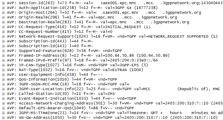
Figure 15. Credit Control Request
[10] Upon
receiving the CCR, the PCRF determines the PCC rule based on the
received subscriber's information and responds with Credit-Control-Answer (CCA) including a PCC rule(s). When it comes to
a default bearer, the PCRF may include only a PCC rule name which indicates the
predefined PCC rule locally stored in the PGW. Henceforth, the PCC rule is
applied to all the traffic by the PGW.

Figure 16. Credit Control Answer
[11] The
SGW/PGW completes the GTP-C session creation procedure by sending the Create
Session Response. The Create Session Response contains the
following parameters:
- AMBR : Aggregated maximum bit rate that is
allowed for this APN
- EPS Bearer ID : 5
- Protocol Configuration Options (PCO) : P-CSCF IP
address, DNS IP address, etc, based on the requested configuration
information by the UE in the Attach Request
- PDN Address Allocation (PAA): UE’s IP address
- SGW GTP-C TEID : Identifier of the SGW as
the end point of the GTP-C tunnel
- Bearer Context: the information of the S1-U
default EPS bearer to be created, which contains EBI, SGW GTP-U TEID, QCI,
etc

Figure 17. Create Session Response
III. Default
EPS bearer creation
Once the
signaling path is successfully set up, the MME requests the eNB to activate the
default EPS bearer with the SGW and the UE. The eNB establishes S1 bearer
towards SGW and the Data Radio Bearer (DRB) towards the UE. The SGW will also establish
the S5 bearer with the PGW, which is not shown in this flow.

Figure 18. Default EPS bearer creation
flow
[12] The MME
accepts the initial attach request by sending the Attach Accept and
requests to activate the default EPS bearer to the UE which contains Activate
default EPS bearer context request in the ESM message container. The
NAS message (i.e., Attach Accept in EMM layer, Activate
default EPS bearer context request in ESM layer) contains the
following parameters.
- TAI list : the list of Tracking Area Identity
within which the UE doesn't need to send Tracking Area Update (TAU)
- EPS QoS : QCI (9)
- Access Point Name (APN) : Internet APN
- PDN address: the allocated UE IP address
- APN-AMBR: the maximum aggregated bit rate allowed
for this APN
- Protocol Configuration Options (PCO) : DNS IP
address, etc, based on the requested configuration information by the UE
in the Attach Request

Figure 19. Attach Accept (Activate default
EPS bearer context request)
The above NAS
message is contained in the Initial
Context Setup Request message on S1AP interface. Other than the NAS
message, it also contains the following parameters.
- UE-AMBR : Aggregated maximum bit rates for the UE
(UL/DL)
- E-RAB ID : identifier of the radio access bearer
towards the eNB
- SGW GTP-U TEID : identifier of SGW as an end
point of the GTP-U tunnel which was delivered in Create Session Response (step#11).

Figure 20. Initial UE Context Request
Upon
receiving the Attach Accept and RRC Connection
Reconfiguration, the UE establishes a DRB with the eNB and responds
with RRC Connection Reconfiguration Complete to the eNB.
The eNB
establishes the uplink S1-U bearer with the SGW. After successful GTP-U
establishment, the eNB responds with the initial
UE Context Response to the MME. In this response, the eNB contains the eNB
GTP-U TEID, which will be routed to the SGW via the MME and used to identify
the eNB as an end point of the GTP-U by the SGW.
NOTE The SGW
GTP-U TEID is generated by the SGW and transparently routed to the eNB via the
MME contained in Create Session Response
and Initial Context Setup Request on
S11 and S1AP, respectively. In the same way, the eNB GTP-U TEID is generated by
the eNB and transparently routed to the SGW via the MME contained in the Initial Context Setup Response and Modify Bearer Request at step#14.

Figure 21. Initial UE Context Response
[13] The UE confirms
the Attach Accept and informs the MME of the fact that the
default EPS bearer has been activated by sending the Attach Complete, which
contains the Activate Default EPS Bearer Context Accept as a response to a corresponding request.

Figure 22. Attach Complete (Activate
default EPS bearer context accept)
[14] The MME
sends the Modify EPS Bearer Request requesting the SGW to
establish the downlink S1 bearer towards the eNB. The Modify EPS Bearer
Request contains the following parameters:
- EPS Bearer ID : identifier of a default EPS
bearer (5)
- eNB GTP-U TEID : identifier of the eNB as an end
point of the GTP-U tunnel

Figure 23. Modify EPS bearer request
Upon
receiving the Modify EPS Bearer Request, the SGW establishes the S1
bearer towards the eNB.
[15] The SGW
responds with the Modify EPS Bearer Response.

Figure 24. Modify EPS bearer response
IV. PDN
Connection to IMS APN
So far, the UE
has performed the initial attachment procedure with the LTE network and as a
result, the PDN connection has been established between the UE and the default
APN, i.e., internet APN. After successful PDN connection with the default APN,
if the default APN is not an IMS APN, the VoLTE UE initiates an additional PDN
connection procedure with the “IMS” APN.

Figure 25. PDN connection with IMS APN
flow
[16] The UE
requests to establish an additional PDN connection with the IMS APN, which is
typically used for VoLTE. There is no need of establishing RRC connection at
this stage as it was already established at step#3. In this message, the Access
Point Name (APN) is set to “IMS” and the UE may request the P-CSCF address and
it is indicated by the Protocol Configuration Option (PCO) parameter. The
following snapshot shows an example of PDN
Connectivity Request which is contained by the uplinkNASTransport S1AP message.

Figure 26. PDN connectivity request for
IMS APN
[17] Upon
receiving the PDN Connectivity Request,
the MME sends Create Session Request
to the SGW. Refer
to step #8 for overall description.
- APN : “IMS”
- MME GTP-C TEID: the same TEID that was allocated at
step #8. The MME and the SGW use the same TEID for different PDNs.
- EPS Bearer ID (EBI): ‘6’ in this case as the EBI ‘5’
was already used in step#8. The EBI will be incremented along with a new
EPS bearer.
- QoS Class Identifier (QCI): ‘5’ for IMS signaling.

Figure 27. Create Session Request
[18] Upon
receiving the Create Session Request,
the MME sends CCR to the PCRF. Refer
to step #9 for overall description.

Figure 28. Credit-Control-Request
- CC-Request-Type AVP: “INITIAL REQUEST”
- Framed-IP-address AVP: The UE IP address is different
from what was allocated at step #9. The UE
is allocated with different IP address per PDN.
- Call-Station-Id AVP: IMS APN
- Default-EPS-Bearer-QoS AVP: In case of IMS APN, the
default EPS bearer has a QCI=5.
[19] Upon
receiving the CCR, the PCRF responds
with CCA containing the PCC rule of
the default EPS bearer for IMS APN. Refer to step #10 for overall description.

Figure 29. Credit-Control-Answer
[20] Upon
receiving the CCA, the MME responds
with Create Session Response
containing the PCC rule of the default EPS bearer for IMS APN. Refer to step
#11 for overall description.
- EPS Bearer ID: ‘6’
- Protocol Configuration Options (PCO)
contains P-CSCF IP address and will be delivered to the UE.
- PDN Address Allocation (PAA): UE’s IP
address and will be delivered to the UE.
- SGW GTP-C TEID: The
same TEID that was allocated at step #11. The MME and the SGW use the same
TEID for different PDNs.
- Bearer Context contains the SGW GTP-U TEID for
the default EPS bearer which is different from what was used in step #11.

Figure 30. Create Session Response
[21] Upon
receiving the Create Session Response,
the MME requests to activate the default EPS bearer by sending Activate default EPS bearer context request
towards the UE, which is contained in E-RAB
Setup Request on S1AP interface. The E-RAB
Setup Request is used to assign resources on Uu (i.e., air interface
between UE and the eNB) and S1 for one or several E-RABs. The following shows
parameters contained in the E-RAB Setup
Request.
- UE-AMBR (UL/DL): The aggregated maximum bit rate
of the UE associated with the same PDN.
- E-RAB to be setup parameters contains E-RAB ID=6
and SGW GTP-U TEID which was delivered at step #20.
The following
shows parameters contained in the Activate
default EPS bearer context request:
- EPS QoS QCI = 5
- Access Point Name (APN): “IMS”
- PDN address: The newly allocated UE IP address
- Protocol Configuration Options (PCO) contains the
P-CSCF address which was delivered in step #20.
- APN-AMBR: aggregated maximum bit rate for the
same APN.

Figure 31. E-RAB Setup Request (Activate
default EPS bearer context request)
The eNB
delivers the Activate default EPS bearer
context request transparently to the UE, which is contained in RRC Connection Reconfiguration. Refer to
step #12 for UE behavior after receiving RRC
Connection Reconfiguration.
[22] ] The UE
informs the MME of the fact that the default EPS bearer has been activated by
sending the Activate Default EPS Bearer Context Accept as a response to a corresponding request.

Figure 32. Activate default EPS bearer
context request

Figure 33. EPS bearer creation flow
[23] The MME
sends the Modify Bearer Request requesting the SGW to
establish the downlink S1 bearer towards the eNB. Refer to step #14 for overall
description. The message contains eNB GTP-U TEID that shall be used by the SGW
to identity the end point of the GTP-U of default EPS bearer.

Figure 34. Modify Bearer Request
[24] Upon receiving
the Modify Bearer Request, the SGW
establishes a downlink S1 bearer and responds with Modify Bearer Response.

Figure 35. Modify Bearer Response
Consequently,
the default EPS bearer with QCI value of ‘5’ between the UE and the IMS APN is
established. Hereafter all the SIP traffic goes through the default EPS bearer.
Red Mouse
REFERENCES
[1] 3GPP
TS25.331, "Radio Resource Control (RRC); protocol specification",
v12.3.0, Sep 2014
[2] 3GPP
TS24.301, "Non-Access-Stratum (NAS) protocol for Evolved Packet System
(EPS); stage3", v12.4.0, Mar 2014
[3] 3GPP
TS36.413, "Non-Access-Stratum (NAS) protocol for Evolved Packet System
(EPS); stage3", v12.4.0, Mar 2014
[6]
Netmanias, "LTE Security II: NAS and AS security", Aug 5th 2013
[7]
Netmanias, "LTE IP Address Allocation Schemes I: Basic", Feb 13th
2015
Last Update: Dec 30th 2015
Great Explanation Hong. I need to understand more about how RRC connection get established between UE and EnodeB it would be great if you can share a link where its explained. and more silly question P-GW assigns IP to UE later so from which IP first UE sends Attach request and PDN connectivity request.
ReplyDeleteThanks in Advance
I'm afraid I couldn't find a web link where RRC interface has been clearly explained aside from the specification (TS 25.331). As for an Identifier, "eNB UE S1AP ID" and "IMSI" are contained in the initialUEMessage (S1AP layer) and Attach Request (NAS layer) respectively. I GUESS the identifier between UE and the eNB could be MAC address considering the protocol structure between them. However, I'm not a radio expert. Hope you can find a better one for radio.
DeleteThanks Hong
DeleteDetailed explanation fortified with PCAP trace. Well done. Thanks a lot.
ReplyDeleteGreat explanation, thanks a lot Hong.
ReplyDeleteI need to know if the steps 9 & 18 have the same Session-Id or not (...14304044....)?
Thanks.
They are different as the APN is different.
DeleteDo you know why some smartphones supporting VoLTE in the market, but they are sending "CS Voice Only" in the attach request (e.g Galaxy S5, Galaxy S6, Galaxy S6 Edge, iPhone 6S,..)
ReplyDeleteIs there any limitation from Samsung or Apple on specific operators?
How we can solve this problem?
Thanks a lot.
In my understanding, it's up to operators. Some operators may use LTE as a data network but still use CS for voice.
DeleteHi, what happens in case of LTE capable but non-VoLTE handsets, do we see a Homogenous-support-of-IMS AVP included or not?
DeleteNo, you need to upgrade your phone or by using app u can make your phone volte... Like jio voice app..
DeleteNice article,
ReplyDeleteInstead of MME, SAEGW need to be mentioned in in CCR & CCA explanation.
I guess there is a mistake in the step 18, actually PGW should send CCR to the PCRF :
ReplyDelete[18] Upon receiving the Create Session Request, the MME sends CCR to the PCRF. Refer to step #9 for overall description.
yes it looks like typo error...
Deleteundoubtedly the best blog available on lte!
ReplyDeleteBest blog ever for lte
ReplyDeleteHello
ReplyDeleteGood Information
I would like to know more about SIP information for IMS registration
Can u help me?
What information you need on IMS Registration. Do you have any specific questions of you need to understand the overall procedure of IMS registration..?
Delete
ReplyDeleteThanks for the Explanation.
Once the EPS default bearer created then the traffic will be flow from UE to PCSCF directly for both registration and voice calls ?
Will MME/PGW/SGW play any role during registration and voice call between UE to PCSCF ? If its play any role, could you please clarify in detail.
Once the EPS default bearer created then the traffic will be flow from UE to PCSCF directly for both registration and voice calls ?
DeleteBR>> Once the 2nd Default bearer (IMS) is created, the REGISTER/INVITE (calls) uses the UL TEIDs (GTP-U:: from UE to eNB to SAEGW) and then reach the PCSCF.
Will MME/PGW/SGW play any role during registration and voice call between UE to PCSCF ? If its play any role, could you please clarify in detail.
BR>> Refer to VOICE call flow from Hong in the same blog. U will understand.
hi Hong,
ReplyDeleteCan u please let me know the flow, What will happens if data will exhaust in VoLTE.
As i know call will be working properly but data speed got reduced like unable to browse . As i understand speed will degraded but internet bearer will not released in CCR U.
hope u understand my query, please help me to understand the flow properly like you explain complete volte flow. Thanks in advance.
Dear
ReplyDeleteIn my case :
RRC request -> RRC Connection setup -> RRC Connection setup complete.
Then RRC Reconfiguration -> RRC Reconfiguration Complete in UL.
Then i get "DL ESM Modify EPS Bearer Context Request".
Does anyone have any ideas on this "Modify EPS Bearer Context Request" message ? Thank you in advance.
Dir: D,
Protocol: EMM,
Msg Type: 201,
Msg Name: Modify EPS bearer context request,
Msg Body: 5200C95B010630100B911F7196FEFE7
EPS Bearer Id: 5,
Protocol discriminator: EPS Session Managment
Procedure transaction identity: 0
Message Type: Modify EPS Bearer Context Request
EPS QoS
- .QoS QCI: 6
IE: Quality of Service:
- .Delay Class: Delay class 1,
...
Hi,
ReplyDeleteStep-18; IMS bearer creation procedure, there is a TYPO. Its PGW sends CCR to PCRF not 'MME seds CCR to PCRF'
[18] Upon receiving the Create Session Request, the MME sends CCR to the PCRF. Refer to step #9 for overall description.
who is giving p-cscf address to UE? who is assigning ip addresss to UE?
ReplyDeletePgw assigns pcscf address to in pcscf discovery procedure
ReplyDeletevery nice explanation
ReplyDeleteEXCELLENT BLOG, I REFER IT OFTEN
ReplyDeleteFlow Speed Test
ReplyDeleteEPB Speed Test
ReplyDelete
ReplyDeleteNon-VoIP numbers from SMSPortal are ideal for simple OTP verification! dependable, safe, and compatible with all main systems. Strongly advised for easy online verification!
Non-VoIP number for verification