Once the UE attaches to the LTE network and the default EPS
bearer is created successfully with the IMS APN, the UE registers to the IP
Multimedia Subsystem (IMS) network before accessing the VoLTE service. The
IMS registration procedure includes the IMS authentication, e.g., IMS-AKA, and
security negotiation between UE and IMS network. After successful IMS
registration, the IMS network becomes aware of UE context such as
subscription profile, registration status, etc. After the initial IMS
registration, the UE shall refresh the IMS registration status by
periodically sending re-Registration.
|
Introduction
It is assumed
that the UE has established a PDN connection to the IMS APN with the QCI value of
its default EPS bearer set to ‘5’. The IMS registration signal goes through the
default EPS bearer and gets inside the IMS core via the P-CSCF. The P-CSCF,
I-CSCF and the S-CSCF consists the IMS core and they controls SIP signaling for
VoLTE. The I-CSCF and the S-CSCF interworks with the HSS via Diameter Routing
Agent (DRA) to retrieve subscriber’s profile, authentication vector, etc. At
the front of the P-CSCF lies the Session Border Controller (SBC). The SBC
provides a security function like IPSec, topology hiding, media controlling,
etc. It can either be co-deployed with the P-CSCF or separated from the IMS
Core.
NOTE the DRA between
Diameter clients and Diameter servers (i.e., PCRF, HSS) is omitted in the
diagram to clarify the reference points.

Figure 1. Overall architecture
I. IMS Authentication and Key Agreement (AKA) during IMS
registration
The IMS AKA
is a mutual authentication methodology used by the IMS network to authenticate
a UE. In this authentication procedure, both server and client runs the same
authentication algorithm using the same secret key and several public
parameters. The secret key is known to both UE and the IMS network. It can be stored
in IP Multimedia Services Identity Module (ISIM) and at the same time, be
provisioned to the Home Subscriber Server (HSS) in advance. After running the
authentication algorithm, the server and the client exchanges their outcome
with each other and authenticate the peer by comparing the received
authentication parameter with the outcome of their own. The following is the
conceptual diagram of the IMS AKA mechanism.

Figure 2. IMS AKA
(1) The secret-key K and the sequence number SQN are commonly
stored in both server and client.
(2) The UE sends the initial registration with the user
identifier towards the IMS Core.
(3) The S-CSCF (i.e., registrar) queries the HSS for the
authentication vector of that subscriber. The HSS generates the random number
RAND using the SQN. The HSS uses K, SQN and RAND parameters as input to the
authentication algorithm and as a result, obtains a set of authentication
parameters, i.e., the authentication vector (AV), as listed below:
- AUTN : Authentication token represented as a concatenation of MAC
and SQN and used by the client to authenticate the server.
- XRES: Expected correct result of running authentication algorithm
and used by the server to authenticate the client.
- CK: Cipher Key (Optional)
- IK: Integration Key
The S-CSCF returns AV (i.e., RAND, AUTN, CK, IK) to the
P-CSCF and the P-CSCF delivers RAND and AUTN in the response to the initial
registration request (see the step#31 for the detail). XRES is stored in the
S-CSCF for later use. The CK and IK is used for integrity and security check by
the P-CSCF (or SBC).
(4) The UE extracts MAC and SQN from the received AUTN. The UE
verifies the range of SQN and uses AUTN, K and RAND as input to the
authentication algorithm. The UE compares the resulting parameter, XMAC with
the received MAC. As such, the UE authenticates the server.
(5) The resulting RES is sent back to the server. The S-CSCF
authenticates the client by comparing the received RES with the XRES.
II. IMS registration procedure
Right after
the default EPS bearer is established, comes IMS registration procedure. The
IMS registration is the procedure for a VoLTE client to register its contact
information to the IMS network and it is performed through the existing EPS
bearer of QCI=5 in general. The IMS registration procedure is composed of two
transactions, that is, the first one is for the UE to obtain the authentication
challenge and the other one is to be authenticated using the received
authentication challenge.
In case it is
a re-registration, the first transaction may not be necessary. The UE will
include challenge parameters received in the previous registration procedure so
the network is able to authenticate the UE as long as the challenge parameters
are still valid. During the registration, the VoLTE client and the IMS network
authenticate each other based on the agreed authentication algorithm and in the
meantime, negotiate a security algorithm for IP layer transactions.

Fig 3. IMS registration flow
|
[25] The UE
initiates the IMS registration by sending the SIP REGISTER towards the P-CSCF.
- Authorization: Authentication information e.g.,
authentication scheme, nonce, realm, authentication algorithm, etc. The
nonce value is empty as this is the first registration.
- Expires: The validity time of this
registration. The UE is supposed to perform re-registration before the
timer is expired. It is usual for the UE to re-register after 1/2*(timer
value) seconds. When the UE is connected to the LTE network, the value of
this header would be 3600 seconds and when it is connected to the Wi-Fi,
it would be 60 seconds typically.
- Security-Client: A list
of supported security algorithm by the UE.
- Contact: UE IP
address, device capabilities and various feature tags.
The following
snapshot shows an example of SIP REGISTER.

Fig 4. SIP REGISTER
|
The P-CSCF
routes the SIP REGISTER to the I-CSCF as the P-CSCF does not
know at this moment as to which S-CSCF is going to serve this UE yet.
[26] Upon
receiving the SIP REGISTER,
the I-CSCF performs user registration status query by sending User-Authorization-Request (UAR) to the HSS.
- User-Name AVP: IMS
Private User Identity (IMPI) of the user and used to authenticate the user
based on the username part of the value.
- Public-Identity AVP: IMS Public User Identity, which is either
SIP URI or TEL URI of the user.
- Visited-Network-Identifier
AVP: The domain of the visited PLMN
The following
snapshot shows an example of UAR.

Fig 5. User Authorization Request (UAR)
|
[27] The HSS
authorizes the user for IMS service (i.e., verifying the user’s IMPI and IMPU)
and if successful, returns with the S-CSCF address for this user in the
response, User-Authorization-Answer (UAA).
- Server-Name AVP: The
S-CSCF address assigned for the IMS subscriber.
- Experimental-Result:
DIAMETER_FIRST_REGISTRATION if it is the first time IMS access for the
user and there is no S-CSCF assigned yet. If there is already assigned
S-CSCF for the user, it will be set to DIAMETER_SUBSEQUENT_REGISTRATION
and the Server-Name AVP will be provided.
The following
snapshot shows the case where there is already assigned S-CSCF for the user, in
which case the I-CSCF does not have to assign a new S-CSCF. If there is no
assigned S-CSCF for the subscriber, the HSS returns a set of S-CSCF
capabilities and the I-CSCF shall assign a new one based on the received
capabilities.

Fig 6. User Authorization Answer (UAA)
[28] The
I-CSCF forwards the SIP
REGISTER towards the indicated
S-CSCF.
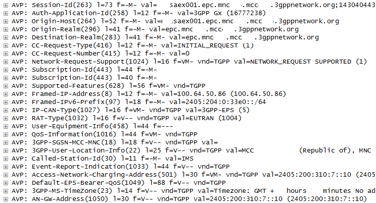
[29] The
S-CSCF sends the Multimedia-Auth-Request (MAR) to the HSS requesting the
authentication information.
- User-Name AVP: IMS
Private User Identity (IMPI) of the user and used to authenticate the user
based on the username part of the value.
- Public-Identity AVP: IMS Public User Identity, which is either
SIP URI or TEL URI of the user.
- SIP-Auth-Data-Item
AVP: The authentication algorithm set to “Digest-AKAv1-MD5” in this
example.
- SIP-Number-Auth-Items
AVP: The number of authentication vectors.

Fig 7. Multimedia Auth Request (MAR)
[30] The HSS
responds with the Multimedia-Auth-Answer (MAA) containing
the authentication information.
- SIP-Authorization
AVP: XRES, which is one of output obtained after running the
authentication algorithm (e.g., AKAv1-MD5).
- SIP-Authenticate AVP:
The concatenation of RAND and AUTN to be used for authentication.

Fig 8. Multimedia Auth Answer (MAA)
[31] The
S-CSCF responds with the 401
UnAuthorized to the P-CSCF.
The WWW-Authenticate header includes nonce parameter (i.e., a concatenation of RAND
and AUTN), IK and CK. The AUTN is a concatenation of the MAC and SQN.
- WWW-Authenticate: Authentication
challenge needed for mutual
authentication.

Fig 9. 401 UnAthorized
[32] The
P-CSCF responds with the 401 UnAuorized
towards the UE. The WWW-Authenticate header includes nonce value. The IK and CK
is stored in the P-CSCF and removed from the WWW-Authenticate header. As the UE
and the P-CSCF negotiated the security method to use IPsec during the initial
SIP registration, the subsequent registration and the call related signals like
INVITE, 200 OK, PRACK, BYE, etc. are secured based on IPsec.
- Security-Server:
a list of supported security algorithm by the server.
NOTE In this
field test, the SBC takes over security functions of P-CSCF. Therefore the
security negotiation and maintaining security parameters like IK and CK are
done by the SBC.

Fig 10. 401 UnAthorized
Upon
receiving the 401 UnAuthorized,
the UE extracts the MAC and the SQN from the AUTN, calculates its own XMAC and
checks if the XMAC is the same as the received MAC and if the SQN is in a
correct range, thereby the UE authenticates the server. The UE also obtains the
RES, IK and CK as a result of running the authentication algorithm.
[33] The UE
sends the subsequent SIP REGISTER towards the P-CSCF and the P-CSCF
to the I-CSCF.
- Authorization header:
The response to the authentication challenge along with the private user
identity, realm, nonce, URI and RES.
- P-Access-Network-Info:
The radio access technology and radio cell identity.

Fig 11. Subsequent SIP Registration
NOTE the
above snapshot has been captured between SBC and P-CSCF as the packet on SGi/Gm
interface has been secured using IPsec as a result of security negotiation and
it couldn’t be decoded by the wireshark in this test. In order to complete the
security negotiation, the UE must have included the Security-Verify header in
the subsequent REGISTER indicating IPsec, which is not shown in this snapshot
as the SBC removes the header before forwarding the message to the IMS core.
[34] Upon
receiving the SIP REGISTER,
the I-CSCF performs user registration status query by sending User-Authorization-Request (UAR) to the HSS.

Fig 12. User Auth Request (UAR)
[35] The HSS
authorizes the user for IMS service (i.e., verifying the user’s IMPI and IMPU)
and if successful, returns with the S-CSCF address for this user in the
response, User-Authorization-Answer (UAA).

Fig 13. User Auth Answer (UAA)
[36] The
I-CSCF forwards the SIP REGISTER towards the indicated S-CSCF. Upon
receiving the subsequent SIP REGISTER, the S-CSCF compares the stored XRES with
the received RES (i.e., Digest Authentication response parameter). If they are
identical and successfully authenticated, the public user identity is
registered in the S-CSCF.
[37] The
S-CSCF informs the HSS that the user has been registered by sending Server Assignment Request (SAR).
Upon receiving the SAR,
the HSS stores the mapping relation between the S-CSCF and the corresponding
IMS subscriber.
- User-Data-Already-Available
AVP: Indicator of whether or not
the sending S-CSCF has user profile information which is required to
service the user. If it is set to USER_DATA_NOT_AVAILABLE, the HSS is
expected to provide the user data in the response.

Fig 14. Server Assignment Request (SAR)
[38] The HSS
responds with the Server
Assignment Answer (SAA) to
the S-CSCF. As it was indicated in the SAR that the S-CSCF does not have user
profile, the HSS includes the User-Data AVP in the response.

Fig 15. Server Assignment Request (SAA)
The User-Data
AVP may contain the following items as is shown below:
- Private Id
- Service Profile
- Public Identity
- a list of initial
Filter Criteria (iFC)

Fig 16. User Data in SAA
[39] The 200 OK for the SIP REGISTER is sent back towards the UE
following the reverse signaling path.

Fig 17. 200 OK to SIP EGISTER
NOTE the
above message has been captured on the interface between SBC and P-CSCF as the
200 OK on SGi/Gm interface has been secured using IPsec.
After successful
IMS registration, the UE subscribes to the reg event package for the public
user identity registered at the S-CSCF. The UE will get notified of a
registration status of public identities belonging to the same user.

Fig 18. Subscription for reg event package
[40] The UE
subscribes to the reg event package by sending SIP SUBSCRIBE towards the S-CSCF.
- Event: “reg”
indicating this is the subscription to the reg event package
- Expires: Validity
time period during which this subscription session is valid..

Fig 19. SIP SUBSCRIBE
[41] The
P-CSCF forwards the SIP SUBSRIBE to the S-CSCF which is known to P-CSCF during
the registration procedure.
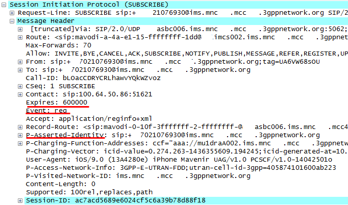
Fig 20. SIP SUBSCRIBE
[42-43] The
S-CSCF returns with the 200 OK response and it is forwarded to the UE following
the signaling path.

Fig 21. 200 OK response to SIP SUBSCRIBE
[44-45] The
S-CSCF notifies the UE of its current registration status by sending SIP
NOTIFY, which is forwarded to the UE

Fig 22. SIP NOTIFY
[46-47] The
UE responds with 200 OK response towards the S-CSCF.

Fig 23. 200 OK response to SIP NOTIFY
REFERENCE
[1] IETF
RFC4740, "Diameter Session Initiation Protocol (SIP) Application",
Nov 2006
[2] IETF RFC3310,
"Hypertext Transfer Protocol (HTTP) Digest Authentication Using
Authentication and Key Agreement (AKA)", Sep 2002
[3] IETF
RFC7315, "Private Header (P-Header) Extension to the Session Initiation
Protocol (SIP) for the 3GPP", July 2014
[4] IETF RFC3329,
"Security Mechanism Agreement for the Session Initiation Protocol
(SIP)", Jan 2003
[5] 3GPP TS
29.228, "IP Multimedia (IM) Subsystem Cx and Dx interfaces; Signaling
flows and message contents", v12.3.0, Sep 2014
[6] 3GPP TS
29.229, "Cx and Dx interfaces based on the Diameter protocol; Protocol
details", v12.6.0, Jun 2015
[7] 3GPP TS
24.228, "Signaling flow for the IP multimedia call control based on
Session Initiation Protocol (SIP) and Session Description Protocol (SDP)",
v5.15.0, Sep 2006
[8] 3GPP TS 33.203,
"3G Security; Access security for IP-based services", v12.5.0, Mar 2014
Last Updated: 8th Mar 2016


