6/30/2015

VoLTE: Bearer binding and Session binding

The LTE supports the PCC(Policy and Charging Control) architecture for QoS control applied to service data flow. In the PCC architecture, the PCRF(Policy and Charging Rules Function) takes the role of a central network component interacting with P-CSCF, SPR(Subscription Profile Repository) and the EPC. The PCRF is always involved in the activities of EPS bearer creation by generating the PCC(Policy and Charging Control) rules and provisioning them to PDN GW(i.e., PCEF). In order to generate PCC rules, the PCRF needs to gather service data flow information from the P-CSCF and possibly the subscription information from the SPR. As the PCC rule shall be applied from the access network to the EPC core with consistency, the PCRF needs to be able to maintain the relations of different sessions over different interfaces across the IP-CAN, EPS bearer and applications, in which the binding mechanism becomes a basic concept.

NOTE In this article, it is assumed that the S5 between the SGW(Serving GW) and PGW(PDN GW) is using GTP, where the PGW becomes the end point of the GTP tunnel.


I. Session binding

The session binding is an association of the AF session information to one and only one IP-CAN session [TS23.203]. Th AF(Application Focus) session is defined as a service level session such as IMS service session that is established by the application level signaling protocol offered by the AF that requires a session-setup with explicit session description before the use of the service[TS29.214].


The IP-CAN session information is obtained by the PCRF during the UE initial attach procedure.
When the UE performs the initial attach to the LTE network, the PGW triggers the CCR-I towards the PCRF. The CCR-I contains the IP-CAN related AVPs such as Framed-IP-Address, IP-CAN-Type, RAT-Type, Called-Station-Id, AN-GW-Address. The following is an example of CCR-I captured over Gx.


  • Framed-IP-Address: The valid routable IPv4 address that is applicable for the IP Flows towards the UE at the PCEF. The PCRF shall use this address to identify the correct IP-CAN session binding[TS29.214].
  • Freamed-IPv6-Prefix: A valid full IPv6 address that is applicable to an IP flow or IP flows towards the UE at the PCEF. The PCRF shall use this address to identify the correct IP-CAN session binding[RFC4005,RFC3162].
  • IP-CAN-Type: Type of Connectivity Access Network in which the user is connected[TS29.212]. 
  • RAT-Type: The Radio Access Technology that is currently serving the UE[TS29.212].
  • Called-Station-Id: APN [TS29.212].

The service data flow information is obtained while the service session is set up. Upon UE request for VoLTE call setup, the SIP INVITE is delivered to the P-CSCF(i.e., AF) with an SDP offer. The SDP offer includes media session information such as 5-tuples(source ip address, destination ip address, source port, destination port and protocol), codec information, etc. Upon receiving the SIP INVITE, the P-CSCF interprets the received SDP contents into diameter AVPs and triggers the AAR towards the PCRF. The following shows an example of SDP contents included in the SIP INVITE.

NOTE It would be possible for the P-CSCF to trigger AAR once when the 183 Session In Progress is received(SDP answer) in order to reduce diameter traffic.


The following is an example of diameter AAR over Rx which includes the service data flow information.


  • Media-Sub-Component: contains the requested bitrate and filters for the set of IP flows identified by their common Flow-Identifier[TS29.212].
  • Flow-Description: defines a packet filter for an IP flow with the following information[TS29.212].
  • Flow-Status: describes whether the IP flow(s) are enabled or disabled[TS29.214].
  • Max-Requested-Bandwidth-UL/DL: Indicates the maximum requested bandwidth in bits per second for an uplink/downlink IP flow[TS29.214].
  • RS-Bandwidth: indicates the maximum required bandwidth in bits per second for RTCP sender reports within the session component[TS29.214].
  • Codec-Data: contain codec related information known at the AF[TS29.214].

Upon receiving the AAR, the PCRF binds the service data flow information received from the P-CSCF to a specific IP-CAN session received from the PGW.


II. Bearer Binding

The bearer binding is the association of the PCC rule and the QoS rule (if applicable) to an IP-CAN bearer within that IP-CAN[TS23.203]. Upon user's request for voice call, the SIP signals will flow through the EPS bearer of QCI=5 and there will be additional EPS bearer newly established to transfer voice traffic. In the same way as described in the previous section, the PCC rules are generated and provisioned to the PGW by the PCRF. The PGW enforces PCC rules accordingly by performing gating control over service data flow.


The PCC rule contains various parameters that can be used to control service data flow such as Flow-Information, Flow-Status, QoS, etc. The following snapshot shows an example of PCC rule contained in the diameter RAR over Gx for voice traffic.


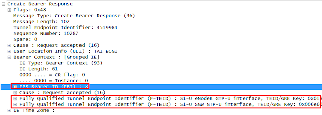
Upon receiving the RAR, the PGW triggers the EPS bearer creation procedure by sending the Create Bearer Request to the MME. The Create Bearer Request contains the TEID for GTP-U created by the PGW and QoS parameters(QCI, MBR, GMBR) as well. In return, the corresponding response from the MME, Create Bearer Response, contains the allocated EBI(EPS Bearer ID) and the TEID for GTP-U created by the eNB. As an end point of the GTP Tunnel, the PGW shall maintain the relations between EPS bearers and PCC rules. The following is an example of Create Bearer Response captured over GTPv2.


***

The session binding and the bearer binding are basic concepts to understand how different type of sessions are related with each other over different interfaces within the PCC architecture. The IP-CAN session to which the UE is attached is bound with the AF session by the PCRF and the service data flow for that AF session is used to generate the PCC rules. These PCC rules are used to map the specific service data flow to a certain EPS bearer which belongs to that IP-CAN session.

Thanks to this binding relations, one event at one place makes a ripple effect to the other, thereby the LTE core can maintain the consistent status for the same UE. If the UE releases an AF session, the corresponding PCC rules for the service data flow belonging to that AF session are removed and in turn, the EPS bearer for that PCC rules will also be released. If the UE detaches from the network, the IP-CAN session will be released and in turn, all the AF session and EPS bearers belonging to the same IP-CAN will also be released.


Red Mouse


6/27/2015

VoLTE: Using TCP parameters in packet analysis

The TCP is used to transfer a continuous stream of octets in each direction between users by packaging some number of octets into segments for transmission through the internet system[RFC793]. In SIP realm, the TCP is one of the most commonly used protocol along with UDP to transfer user data.


The above diagram shows an example of the protocol map for LTE user plane. The backhaul is placed between eNB and the EPC in the operator's network in general. The IPv4 packet sent by the UE over the air is wrapped by the eNB using GTP and IPv6 headers. The eNB sends the IPv6 packet through the GTP tunnel and the PGW at the end of GTP tunnel unwraps the IPv6 and GTP headers. The retrieved IPv4 packet at PGW is forwarded to the P-CSCF over SGi interface.

I. TCP header

The following shows the TCP headers and parameter descriptions as specified in RFC793


  • Sequence Number(32bits): The sequence number of the first data octet in this segment(except when SYN is present). If SYN is present, the sequence number is the initial sequence number(ISN) and the first data octet is ISN+1.
  • Acknowledgment Number(32bits): If the ACK controls bit is set this field contains the value of the next sequence number the sender of the segment is expecting to receive. Once a connection is established this is always sent.
  • Control bits(6bits)
    • URG: Urgent Pointer field significant
    • ACK: Acknowledgement field significant
    • PSH: Push Function
    • RST: Reset the connection
    • SYN: Synchronize sequence number
    • FIN: No more data from sender
  • Checksum(16bits): The 16bit one's complement of the one's complement sum of all 16 bit words in the header and text. This is used to detect the corruption of data over TCP

II. Usage of TCP headers in packet analysis

After successful initial attachment to the LTE network, the VoLTE UE(i.e., IMS UE) establishes a TCP connection with the P-CSCF in order to process the IMS registration. Once the TCP connection is established, the UE starts sending SIP messages(i.e., SIP REGISTER).

TCP parameters can be useful when they are used to identify the identical packets between sending and the receiving node respectively. It is true in particular when the network(e.g., backhaul) is unstable where there can be a lot of packet delay, packet loss and packet re-transmissions, as it becomes far more difficult to analyze the packet flows.

NOTE In the following snapshot, the yellow box depicts a UE side ip address and the green box a Core side ip address. All the detailed ip address is hidden for security purpose.

The following snapshot shows the UE side trace log that was captured at UE. This example shows the normal SIP procedure that can occur when the call is requested by the user.


The following snapshot shows the Core side trace log that was captured between backhaul and the  Serving GW. The procedure in this example is correlated with the above figure.


In order to find the matched transaction between the two nodes, the TCP checksum data can be used to identify the same packet. In this example, the same TCP packet for SIP INVITE can be found with its checksum value = 0x8bef. Note that it would be more usual to find the matched SIP transaction based on Call-Id in normal situation. However, when there are many packet re-transmissions and delays, the Call-Id wouldn't be enough to pinpoint the matched ones.

On the other hand, taking a look at the SIP PRACK, the UE has sent two packets. As they are re-transmitted by the SIP layer, they will have different checksum value. (i.e., ox28e2, 0x2781)


In the meantime, there are three SIP PRACKs appears in the core side and all of them has the same checksum value(0x2781). This checksum value indicates that they are matched only with second SIP PRACK sent by the UE. Therefore it can be reasoned that the first SIP PRACK sent by the UE has been lost somewhere between UE and the Serving GW.


In the following core trace, it is observed that the TCP Ack for the SIP PRACK(TCP Syn) is sent only after 40 ms from the received SIP PRACK. The corresponding TCP Ack can be identified by mapping the TCP Acknowledge Seqnum of the TCP Syn with the Seqnum of the TCP Ack.


The same TCP Ack can also be found based on the checksum value. In this example, the UE received the TCP Ack for the SIP PRACK after 700 ms.


Given the relative time gap between the SIP PRACK(TCP Syn) and the corresponding TCP Ack at both ends, it can be reasoned that there has been a packet delay somewhere in a downlink between  Serving GW and the UE.


***

The TCP packet analysis can be used to correlate the packets between sending node and the receiving node. Measuring the relative time gap of sending and receiving packets also makes it easier to identify the problematic NEs or interfaces. As such, the TCP headers give useful information to engineers in analyzing the technical problems in VoLTE service. As the TCP packet delays and losses can more often than not lead to the IMS registration delay, IMS registration failure, call setup delay and call setup failure, it is directly related to the quality of user experiences. The TCP packet analysis becomes very useful way to realize the quality of VoLTE Service as it might also be in other services.


Red Mouse

6/20/2015

VoLTE: E-RAB management vs Handover

The 3GPP TS36.413 addresses the racing condition between UE handover and the E-RAB management procedures. The UE handover occurs based on the measurement parameters sent by the UE whereas the EPS bearer creation as a part of VoLTE call setup procedure in general. When these two independent events occur at the same time, there can be a collision at eNB, as the eNB is involved in both procedures. In this collision state, the eNB has two options to take as follows:


I. Terminating the E-RAB Setup and continues the UE S1 handover
The following flow shows the eNB rejecting the E-RAB setup request and continues the handover procedure. Upon receiving the rejection to the E-RAB setup request with its cause id, e.g., "S1 intra system Handover Triggered", the MME continues the S1 handover procedure. In the meantime, the Create Bearer Request can be postponed temporarily until the handover is completed. If the Serving GW or MME is to be changed, the Create Bearer Request will be rejected with its cause id set to "Temporarily rejected due to handover" and the P-GW may retry the EPS bearer creation procedure after the S1 handover is completed(refer to http://bit.ly/1H4Z7yr for the detail).


II. Cancelling the UE handover and continues E-RAB Setup
The following shows the eNB cancels the S1 handover towards the MME and continues the EPS bearer creation procedure. Upon receiving the Handover Cancel, the MME terminates ongoing Handover Preparation procedure and release any resources associated with the handover preparation. If the eNB does not receive the Handover Cancel Ack, it is assumed that the handover is terminated successfully.


The following shows the eNB cancels the X2 handover to continue the EPS bearer creation procedure according to 3GPP TS36.423. Upon receiving the Handover Cancel, the target eNB releases any resources reserved for the concerned UE context.


III. Service impact
The eNB shall be able to handle the racing condition between two independent events(i.e., E-RAB setup request and handover) either by cancelling the handover or by rejecting the E-RAB setup request. The MME also needs to be able to handle the racing condition either by rejecting the bearer related requests with a corresponding reason (e.g., Temporarily rejected due to handover) or by possibly providing pause-and-resume mechanism itself for bearer related requests in case the handover is in progress. If the bearer related request is rejected, the PGW may realize the retry mechanism(refer to http://bit.ly/1H4Z7yr for the detail). If this type of racing condition is not handled appropriately, there could be frequent call drops or call setup failures based on eNB optimization status resulting in bad user experiences of VoLTE user.


Red Mouse

6/17/2015

VoLTE: Understanding of GTP TEID to use in LTE trouble shooting

The GTP(GPRS Tunneling Protocol) is a communication protocol used by the LTE to deliver IP packets within the EPC. The GTP-C is used to deliver the controlling signals over S11 and S5, whereas the GTP-U is used to deliver application payload over S1 and S5. 


I. TEID exchanges

The TEID(Tunnel Endpoint IDentifier) is generated by each node during the initial attach procedure. The Create Session Request includes the S11 MME DL TEID and the S5 SGW DL TEID, which are generated and included by MME and Serving GW respectively. The Create Session Response includes the S5 PGW UL TEID and the S11 SGW UL TEID, which are generated and included by PGW and Serving GW respectively.

The following diagram shows the actual call flow and depicts how the TEID is exchanged between NEs. Upon receiving the Create Session Request, the Serving GW establishes the downlink GTP-C tunnel towards the MME using the received S11 MME DL TEID. In the same way the MME establishes the uplink GTP-C tunnel towards the Serving GW using the received S11 SGW UL TEID. The TEID for GTP-U is included in the body of bearer related messages (e.g., Create Bearer Request/Response, Modify Bearer Request/Response). 


The newly generated TEID is included in the body of each sending message and delivered to the peer node. The peer node perceives the end point of the GTP based on the received TEID. When the message goes through the existing GTP tunnel, the TEID of the peer node will be included in the GTP header of the sending message. The following example shows the TEID included in the Create Session Request being sent from the MME towards the Serving GW. 


In the mean time, the following example shows the TEID included in Create Session Response, where the TEID received from the MME is used in the header and the newly generated TEID of Serving GW is included in the body.


II. TEID lifetime

The life time of the GTP-C session lasts along with the life time of the UE's IP-CAN connection. It starts when the UE attaches to network and ends when the UE detaches from the network. In case there are multiple PDNs , there is only one GTP-C session per UE. The following example shows the lifetime of the same GTP-C session, which is defined by same TEIDs. In this example, there are two Create Session Requests, each for different PDNs. Each Create Session Response is followed by the Modify Bearer Request for establishing default EPS bearers. Lastly, the Create Bearer Request is to establish dedicated EPS bearers.


The lifetime of the GTP-U depends on the attributes of the EPS bearer. The GTP-U connection associated with the default EPS bearer has the same lifetime of that of GTP-C connection, whereas the GTP-U connection associated with the dedicated EPS bearer will be dynamically created and deleted within the lifetime of IP-CAN connection.


III. TEID usage

When there are multiple EPS bearers established for the same APN and there needs to verify if  specific service data flow goes through the right EPS bearer, the TEID can be a useful tool to figure it out. The following example shows the GTP-U packet of the SIP REGISTER being sent from the UE towards the IMS Core. The TEID in the GTP header indicates "0x005b8422".


The following shows the same TEID appears in the body of a Modify Bearer Request. This Modify Bearer Request is for the EPS bearer of QCI=5.


Red Mouse

6/16/2015

VoLTE: QCI=1 setup failure when S1 handover is in progress

In a mobile environment, by its nature, the handover may occur while the user is engaged in a VoLTE call session. The UE periodically reports measurements of various parameters to the eNB and the eNB determines whether the handover is required. Once it is determined by the eNB to trigger the handover, the eNB will decide whether to perform X2 handover or the S1 handover. When there is an existing X2AP connection towards the target eNB, the source eNB performs X2 handover. If there is no X2AP connection or the X2 handover attempt has failed for some reasons, the source eNB may trigger the S1 handover.

As to the PGW initiated bearer related requests(e.g., Create/Update/Delete Bearer request) there is no cause-id defined in the 3GPP TS29.274(r8),  Therefore, in this case, the MME may reject the request with the cause-id of reason unspecified. This cause-id will lead to the ripple effect towards the upstream forcing each node on the path to release the corresponding resources. This is shown in the following flow diagram.


Even though the handover is successful in this flow, the error cause of RESOURCE ALLOCATION FAILURE in the CCR over Gx will lead to the PCRF to send RAR(Re-Authentication Request) or ASR(Abort-Session-Request) over Rx with a cause-id of RESOURCE NOT AVAILABLE, and the process will end up with sending the 503 Service Unavailable by the P-CSCF. Upon receiving the 503 Service Unavailable, the UE releases all the resources for the call.

In a circumstance where the eNB is not optimized, the handover might occur relatively often. If this racing condition is not handled properly, the result will lead to bad user experiences for VoLTE as the rejection of the bearer related request may often lead to the VoLTE setup failure for QCI=1 bearer for voice.

In the 3GPP TS29.274(r9), the 3GPP has specified the proper cause value of "Temporarily rejected due to handover in progress" and in the 3GPP TS29.274(r11), "Temporarily rejected due to handover/TAU/RAU procedure in progress". This cause-id value is used by the MME rejecting the bearer related request when the handover results in the relocation of the Serving GW and/or MME. The PDN GW which initiated the bearer related request will be able to consider this error cause value to handle the rejection. 

The following flow shows one example of how to handle the rejected bearer related request. In this flow, the Create Bearer Request is rejected by the MME. The PDN GW may retry the Create Bearer Request based on the operator's policy. 


If there is no need of relocation of MME and/or Serving GW, the MME does not need to respond with the cause-id, rather it can perform store-and-forward way of message handling. In this case, the MME will temporarily store the message and wait for the handover to be completed and if it's done soon enough, the Create Bearer Request can be sent to the UE via the target eNB. How 'soon' is the 'soon enough' time is usually up to the operator's policy.


Red Mouse

6/10/2015

VoLTE: End to end QoS control

The end to end QoS control is an important factor to be considered to provide a qualified service to users. It would become more so when the service is required to be provided in real time such as voice call or multimedia streaming.  If the voice call service is provided through the best-effort network where the QoS is not guaranteed, the users will experience frequent call attempt failure, call setup delay, call drop, voice cracking, etc. 

In the following are introduced several different level of QoS control methodologies for VoLTE service.


I. Separated APN for VoLTE

The UE can attach multiple PDNs at the same time and each PDN connection can have multiple EPS bearers. Each PDN connectivity has one default EPS bearer and can have multiple dedicated EPS bearers up to 11 in total. The UE is assigned with a different IP address for each APN by the P-GW during PDN connectivity procedure for each APN.


In general, the operator uses an IMS APN separately from the Internet APN. This dedicated APN for VoLTE service may have the intention to provide the quality of VoLTE service not to be affected by other non-real time service such as the internet service. The default APN is provided by the network based on subscriber profile fetched from the HSS during the initial attach procedure. 

The following diagram shows a call flow of initial attach procedure. During the initial attach procedure, the MME obtains the APN list from the HSS in the Location Update Answer message as a part of subscriber's profile. The MME determines the default APN based on the received APN list and parameters, creates the GTP-C session with the corresponding S-GW/P-GW. Once the GTP-C session is created successfully, the default APN information is delivered to the UE in the Attach Accept message. If the default APN is pre-configured in the UE, the same should also be the part of the subscriber profile stored in HSS in order to avoid the conflict which leads to the attach failure. If the default APN is not an IMS APN, the UE has to trigger additional PDN Connectivity with its APN parameter set to "IMS".

NOTE the EPS bearer creation procedure is not shown in this diagram. 


The following shows an example of the Location Update Answer message from the HSS which contains the APN list for the subscriber. Each APN-Configuration AVP under the APN-Configuration-Profile AVP contains the APN information. The Context-Identifier AVP which is one of sub AVPs of the APN-Configuration-Profile AVP is used to determine the defalut APN. Whereas, the same AVP under the Configuration-Profile AVP indicates the context identifier for respective APNs. Given this, the APN whose own Context-Identifier is matched with the upper level Context-Identifier will become the defualt APN. 

In this example, there are three APNs in total and the "IMS" APN will be selected as a default APN of which Context-Identifier(=10) has the same value as upper level Context-Identifier.


II. PCC(Policy and Charging Control) rules
When the PDN connection is established with the IMS APN, the EPC and the PCRF creates the EPS bearer of QCI=5 for IMS signaling. Since then, all the SIP signaling in VoLTE goes through this EPS bearer of QCI=5. Subsequently, when the user requests a VoLTE call setup and the media information is exchanged end to end, the EPC and the UE creates dedicated EPS bearer(e.g., QCI=1 for Voice, QCI=2 for Video, etc) to transfer media traffic. 

The PCC architecture consists of P-CSCF(i.e., AF), PCRF, P-GW(i.e., PCEF) and S-GW(i.e., BBERRF). All of these components are involved in delivering the service data flow to the right EPS bearer with the right QoS conditions. The PCC rules generated or assigned by the PCRF define the mapping relations between the QoS paramemters and the service data flows. Upon receiving a VoLTE request(i.e., SIP INVITE with SDP offer), the P-CSCF extracts the 5-tuples of media information(i.e., source ip address, destination ip address, source port, destination port, protocol), codec profile, etc. The P-CSCF interworks these service data flow information to the PCRF and the PCRF either dynamically generates the corresponding PCC rules or assigns the predefined PCC rule. The PCC rules are provisioned to the P-GW. As its logical name suggests(i.e., PCEF), the P-GW performs gating control for the uplink/downlink traffic based on the given PCC rules. After successful PCC provisioning, the P-GW initiates the dedicated EPS bearer creation via the S-GW towards the eNB. 


The following example shows the PCC rule information in the RAR(Re-Authenticate Request) over Gx. In this case, there are two Charging-Rule-Definition AVPs defined each for RTP and RTCP respectively. The Charging-Rule-Definition AVP contains various information that is required for service data control such as PCC rule name(i.e., Charging-Rule-Name AVP), 5-tuple for each direction(i.e., Flow-Information AVP), QoS parameters(i.e., QoS-Information AVP), etc. The QOS parameters includes the QCI, GBR(UL/DL), AMBR(UL/DL), ARP, etc.


  • QCI(CoS Class Index): A level of QoS classified based on the required quality per service usages.
  • GBR(Guaranteed Bit Rate) : The minimum bit rate to be guaranteed for the given bearer. A certain amount of bandwidth will be reserved for this bearer. The GBR bearer always takes up resources over the radio link, even if no traffic is sent.
  • AMBR(Aggregated Maximum Bit Rate) : The total bit rate that is allowed to be used for all non-GBR bearers associated with a specific APN/UE.
  • ARP(Allocation and Retention Priority) : Being used to indicate a priority for the allocation and retention of bearers. It’s typically used to decide whether a bearer establishment or modification can be accepted or needs to be rejected due to resource limitations..

III. DSCP(Differentiated Services Code Point) marking
The DSCP marking is an IP level QoS control for each IP packet to flow through the backhaul with a certain priority and the appropriate latency. As the IP packets from different PDN with different QCI values will be mixed inside the backhaul(e.g., VoLTE, internet), the DSCP marking at IP layer would be an important factor to be considered by switches and routers to guarantee the quality service for VoLTE. Without DSCP marking, IP packets can be delayed or dropped significantly when there is a burst of IP traffic at the same time within the IP network.

The DSCP marking shall be done by both end points of the backhaul for both uplink and downlink IP packets based on the QCI of the service traffic. The following shows a recommended DSCP mapping relations between the QCI and the DSCP values as specified in GSMA IR.34 "Inter-Service Provider IP backbone guidelines". For instance, the IP packets with QCI=1 and 2 for voice and video respectively is marked with the 2E, whereas the IP packets with QCI=5 for IMS signaling will be marked as 1A.

NOTE the DSCP-QCI mapping relation is a part of operator's policy. All the switches and routers aware of DSCP values needs to adjust itself to the correct behavior according to the agreed DSCP values as to handling the IP packets.


The following shows an example of DSCP marking in the IP packet. In this example, the IP packet has been used to deliver the SIP INVITE and the IPv4 packet is wrapped by the IPv6 header at P-GW/S-GW. The 6-bit DS field in this IPv6 header is set to "2e"(i.e.,the Expedited Forwarding). This is a different value from the one specified in the above case 


Red Mouse