The UE initiated detach procedure may occur when the UE is turned off or the UE needs to fall back from EPS services to non-EPS services or vice versa. Along with the detach procedure all the allocated resources are released and connections for signaling and bearer are disconnected.
 The above figure shows the overall sequence of how the UE and the network releases related resources when the UE detaches. Upon receiving the detach request from the UE(1), the MME releases the EPS bearer context towards the S/PGW(2) and in turn, the bearer binding and the session binding is released over Gx and Rx(3,4). Apart from this procedure, the MME also releases the UE context towards the eNB(5) and the eNB releases RRC connection with the UE(6). Meanwhile, the IMS network is informed of bearer release from the PCRF and proceeds the release procedure of the SIP session(7).
I. EPS bearer release
[1] The UE triggers the detach procedure from the LTE network by sending Detach Request towards the MME.


If it is the detach for EPS only or combined EPS/IMSI detach, the MME deactivates the EPS bearer context(s) for this UE locally and enter the state EMM-DEREGISTERED for this UE.
[2-3] The MME requests the S/PGW to delete the corresponding session by sending Delete Session Request. If there are multiple APNs that the UE was attached to, there will be multiple Delete Session Request, one for each APN. The message contains the list of EBIs to be deleted for each APN. In case of detach, all the EBIs belong to that APN shall be included.
Upon receiving the Delete Session Request, the SGW/PGW deactivates the EPS bearer context corresponding to the received EBIs of this UE. The bearer binding relation between EPS bearer and PCC rule is also released. The SGW/PGW responds with the Delete Session Response.
[4] The MME sends Detach Accept only if the Switch off parameter is not "Switch off". Otherwise, this transaction will be spared.
[5] The MME performs MME-initiated UE context release by sending UE Context Release Command to the eNB, which is to release the UE-associated logical connection. In this case, the message contains the cause value of "Detach". Upon receiving the UE Context Release Command, the eNB releases all related signaling and user data transport resources for the indicated UE by the UE S1AP ID.

[6-7] The eNB sends the RRC Connection Release to the UE. In case the RRC connection has not been released already, the RRC Connection Release will be sent as an Acknowledge Mode(AM). After releasing the RRC connection, the UE responds with the RRC Connection Release Complete.
NOTE Whether to use Acknowledge Mode (AM) or UnAcknowledge Mode(UM) is dependent on the requirements for the radio bearer such as packet loss, packet delay, etc. The basic difference between the UM and AM is that the UM would be compared with the UDP where re-transmission control is not provided, whereas the AM is more likely TCP. The detail for this technology may need to be referred to the radio expert.
[8] The eNB responds with the UE Context Release Complete to the MME and releases the S1 signaling connection. This step would be performed without necessarily waiting for the RRC Connection Release Complete from the UE. Upon receiving the UE Context Release Complete, the MME deletes any eNB related information.
II. IMS de-Registration
Once the GTP-C, S1-MME connection and the corresponding S1 bearers have been released, the network starts to release remaining resources and connections towards upstream.
[9-10] The PGW reports the event to the PCRF by sending Credit-Control-Request(CCR). The CCR contains the cause value set to be "TERMINATION-REQ". The "TERMINATION-REQ" is sent only when the IP-CAN session is terminated, i.e., detach. If there are multiple APNs to which the UE attaches, there will be multiple CCRs sent to the PCRF, one for each APN. The PCRF acknowledges with the Credit-Control-Answer(CCA).

[11-12] Upon receiving the CCR from the PGW containing the IP-CAN session termination event, the PCRF releases session binding relation between IP-CAN session and the corresponding AF-session and requests to release the Rx session by sending Abort Session Termination (ASR) to the P-CSCF. The message contains the Abort-cause value of "BEARER_RELEASED". The PCRF acknowledges with the Abort Session Answer (ASA).

[13] Upon receiving the CCR containing the cause value of "BEARER RELEASED", the P-CSCF performs de-registration procedure by sending the SIP REGISTER to the I-CSCF in the UE's home network with its Expires header set to zero. The P-CSCF performs a name-address resolution mechanism for P-Visited-Network-ID header to determine the address of the home network.

[14] The I-CSCF requests the registration state of the received Public User Identity to the HSS by sending the User-Authentication-Request(UAR) with its User-Authorization-Type set to "DE_REGISTRATION". The UAR contains the Public User Identity, Private User Identity, Visited Network Id, etc.

[15] The HSS determines if the user is currently registered and responds with the User-Authentication-Answer(UAA) with the corresponding S-CSCF name (i.e., Server-Name AVP).
[16] The I-CSCF determines the address of the S-CSCF through the name-address resolution mechanism and sends the SIP REGISTER to that S-CSCF.
[17-18] Upon receiving the SIP REGISTER, the S-CSCF may trigger the 3rd-party de-Registration procedure towards the application server based on the iFC mechanism. On the other hand, the S-CSCF sends the Server-Assignment-Request(SAR) towards the HSS. In this example, the Server-Assignment-Type AVP is set to "USER_DEREGISTRATION_STORE_SERVER_NAME", which indicates that the give Public User Identity is no longer considered as registered and the HSS needs to keep the S-CSCF name after this action.

[19-20] The 200 OK for the SIP REGISTER is sent towards the P-CSCF.
[21] The S-CSCF may send the SIP NOTIFY towards the UE to inform that the subscription has terminated. The body of the SIP NOTIFY includes the fact that the registration state has also been terminated. This SIP NOTIFY transaction is correlated with the subscription procedure that was done when the UE registered to this IMS network.

When it comes to IMS de-registration, it is supposed to happen before LTE attach in a normal situation and it would be a quite natural sequence considering the protocol stack. The UE shall release all the resources relating to applications before it detaches from the network. However, in this example, the UE performs LTE detach first and then the IMS Core initiates the IMS de-registration based on the bearer loss event reported from the PGW. This type of exceptional situation happens more often than not in reality. It can come from incomplete implementation of the VoLTE client in a UE or the UE might not be able to perform IMS de-registration for some reasons.
REFERENCES
[1] 3GPP TS24.301, "Non-Access Stratum (NAS) protocol for Evolved Packet System (EPS); Stage 3", v12.4.0, Mar 2014
[2] 3GPP TS29.274, "3GPP Evolved Packet System (EPS); General Radio Packet Service (GPRS) Tunneling Protocol for Control Plane (GTPv2-C); Stage 3", v9.3.0, Jun 2014
[3] 3GPP TS23.401, "General Radio Packet Service (GPRS) enhancements for Evolved Universal Terrestrial Radio Access Network (E-UTRAN) access", v12.4.0, Mar 2014
[4] 3GPP TS23.228, "IP Multimedia System (IMS); stage2", v11.4.0, Mar 2012
[5] 3GPP TS29.229, "Cx and Dx interfaces based on the Diameter Protocol; Protocol details", v12.6.0, Jun 2015
[6] 3GPP TS36.413, "Evolved Universal Terrestrial Radio Access Network (E-UTRAN); S1 Application Protocol (S1AP)", v13.0.0, Jun 2015
I. EPS bearer release
 |
Fig 1. Detach procedure - EPS bearer release |
[1] The UE triggers the detach procedure from the LTE network by sending Detach Request towards the MME.
- Detach Type IE indicates the reason of detach procedure and where the UE is being detached from (i.e., EPS services only, non-EPS services only, both). In this example, the UE is being detached from the LTE network due to switch-off.
- EPS mobile identity IE is set to be GUTI when the UE has a valid GUTI. If the UE does not have the valid GUTI, the EPS mobile identity will be the IMSI.

If it is the detach for EPS only or combined EPS/IMSI detach, the MME deactivates the EPS bearer context(s) for this UE locally and enter the state EMM-DEREGISTERED for this UE.
Upon receiving the Delete Session Request, the SGW/PGW deactivates the EPS bearer context corresponding to the received EBIs of this UE. The bearer binding relation between EPS bearer and PCC rule is also released. The SGW/PGW responds with the Delete Session Response.
[4] The MME sends Detach Accept only if the Switch off parameter is not "Switch off". Otherwise, this transaction will be spared.
[5] The MME performs MME-initiated UE context release by sending UE Context Release Command to the eNB, which is to release the UE-associated logical connection. In this case, the message contains the cause value of "Detach". Upon receiving the UE Context Release Command, the eNB releases all related signaling and user data transport resources for the indicated UE by the UE S1AP ID.
NOTE Whether to use Acknowledge Mode (AM) or UnAcknowledge Mode(UM) is dependent on the requirements for the radio bearer such as packet loss, packet delay, etc. The basic difference between the UM and AM is that the UM would be compared with the UDP where re-transmission control is not provided, whereas the AM is more likely TCP. The detail for this technology may need to be referred to the radio expert.
[8] The eNB responds with the UE Context Release Complete to the MME and releases the S1 signaling connection. This step would be performed without necessarily waiting for the RRC Connection Release Complete from the UE. Upon receiving the UE Context Release Complete, the MME deletes any eNB related information.
II. IMS de-Registration
Once the GTP-C, S1-MME connection and the corresponding S1 bearers have been released, the network starts to release remaining resources and connections towards upstream.
 |
| Fig 2. Detach procedure - application level release |
[9-10] The PGW reports the event to the PCRF by sending Credit-Control-Request(CCR). The CCR contains the cause value set to be "TERMINATION-REQ". The "TERMINATION-REQ" is sent only when the IP-CAN session is terminated, i.e., detach. If there are multiple APNs to which the UE attaches, there will be multiple CCRs sent to the PCRF, one for each APN. The PCRF acknowledges with the Credit-Control-Answer(CCA).

[11-12] Upon receiving the CCR from the PGW containing the IP-CAN session termination event, the PCRF releases session binding relation between IP-CAN session and the corresponding AF-session and requests to release the Rx session by sending Abort Session Termination (ASR) to the P-CSCF. The message contains the Abort-cause value of "BEARER_RELEASED". The PCRF acknowledges with the Abort Session Answer (ASA).

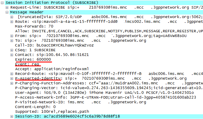
[13] Upon receiving the CCR containing the cause value of "BEARER RELEASED", the P-CSCF performs de-registration procedure by sending the SIP REGISTER to the I-CSCF in the UE's home network with its Expires header set to zero. The P-CSCF performs a name-address resolution mechanism for P-Visited-Network-ID header to determine the address of the home network.

[14] The I-CSCF requests the registration state of the received Public User Identity to the HSS by sending the User-Authentication-Request(UAR) with its User-Authorization-Type set to "DE_REGISTRATION". The UAR contains the Public User Identity, Private User Identity, Visited Network Id, etc.

[15] The HSS determines if the user is currently registered and responds with the User-Authentication-Answer(UAA) with the corresponding S-CSCF name (i.e., Server-Name AVP).
[16] The I-CSCF determines the address of the S-CSCF through the name-address resolution mechanism and sends the SIP REGISTER to that S-CSCF.
[17-18] Upon receiving the SIP REGISTER, the S-CSCF may trigger the 3rd-party de-Registration procedure towards the application server based on the iFC mechanism. On the other hand, the S-CSCF sends the Server-Assignment-Request(SAR) towards the HSS. In this example, the Server-Assignment-Type AVP is set to "USER_DEREGISTRATION_STORE_SERVER_NAME", which indicates that the give Public User Identity is no longer considered as registered and the HSS needs to keep the S-CSCF name after this action.

[19-20] The 200 OK for the SIP REGISTER is sent towards the P-CSCF.
[21] The S-CSCF may send the SIP NOTIFY towards the UE to inform that the subscription has terminated. The body of the SIP NOTIFY includes the fact that the registration state has also been terminated. This SIP NOTIFY transaction is correlated with the subscription procedure that was done when the UE registered to this IMS network.

***
When it comes to IMS de-registration, it is supposed to happen before LTE attach in a normal situation and it would be a quite natural sequence considering the protocol stack. The UE shall release all the resources relating to applications before it detaches from the network. However, in this example, the UE performs LTE detach first and then the IMS Core initiates the IMS de-registration based on the bearer loss event reported from the PGW. This type of exceptional situation happens more often than not in reality. It can come from incomplete implementation of the VoLTE client in a UE or the UE might not be able to perform IMS de-registration for some reasons.
Red Mouse
REFERENCES
[1] 3GPP TS24.301, "Non-Access Stratum (NAS) protocol for Evolved Packet System (EPS); Stage 3", v12.4.0, Mar 2014
[2] 3GPP TS29.274, "3GPP Evolved Packet System (EPS); General Radio Packet Service (GPRS) Tunneling Protocol for Control Plane (GTPv2-C); Stage 3", v9.3.0, Jun 2014
[3] 3GPP TS23.401, "General Radio Packet Service (GPRS) enhancements for Evolved Universal Terrestrial Radio Access Network (E-UTRAN) access", v12.4.0, Mar 2014
[4] 3GPP TS23.228, "IP Multimedia System (IMS); stage2", v11.4.0, Mar 2012
[5] 3GPP TS29.229, "Cx and Dx interfaces based on the Diameter Protocol; Protocol details", v12.6.0, Jun 2015
[6] 3GPP TS36.413, "Evolved Universal Terrestrial Radio Access Network (E-UTRAN); S1 Application Protocol (S1AP)", v13.0.0, Jun 2015
[7] Netmanias, "EMM Procedure 2. Detach", Jan 2014