The service data flow template is a set of packet filters applied to IP packets to identify the service data flow belonging to a specific application. The packet filters typically consist of IP 5-tuples, i.e., source IP address, destination IP address, source port, destination port, protocol type. The service data flow template is delivered to the PGW contained in the PCC rules. The PGW identifies the service data flow based on the service data flow template applied in the order of filtering priorities. Once the service data flow is identified, the corresponding QoS parameters are applied to relate the service data flow to a certain EPS bearer.
I. TFT filter
Once the bearer binding is completed, that is, the PGW builds mapping relations between EPS bearers and the corresponding PCC rules, the PGW requests the creation of the EPS bearer (i.e., Create Bearer Request) towards the MME in which the set of IP 5-tuples are interpreted as a bearer level Traffic Flow Template (TFT). The TFT can be defined either separately for uplink and downlink or for both uplink and downlink. The TFT for the downlink is used by the network element whereas the TFT for the uplink is used by the UE. The following diagram shows the TFT structure when the TFT operation is add, create or replace [TS24.008].

The following snapshot shows the TFT included in the Create Bearer Request (PGW/SGW->MME) captured over S11. The TFT operation code is to "Create a new TFT" and the direction of the IP flow to which this TFT is applied is an "uplink only" as this TFT is supposed to be used by the UE. The precedence value indicates the priority for this filter among other filters to be applied to the IP flow. Therefore this priority value must be locally unique in the UE. In this example, the IPv4 remote address indicates the P-CSCF address.

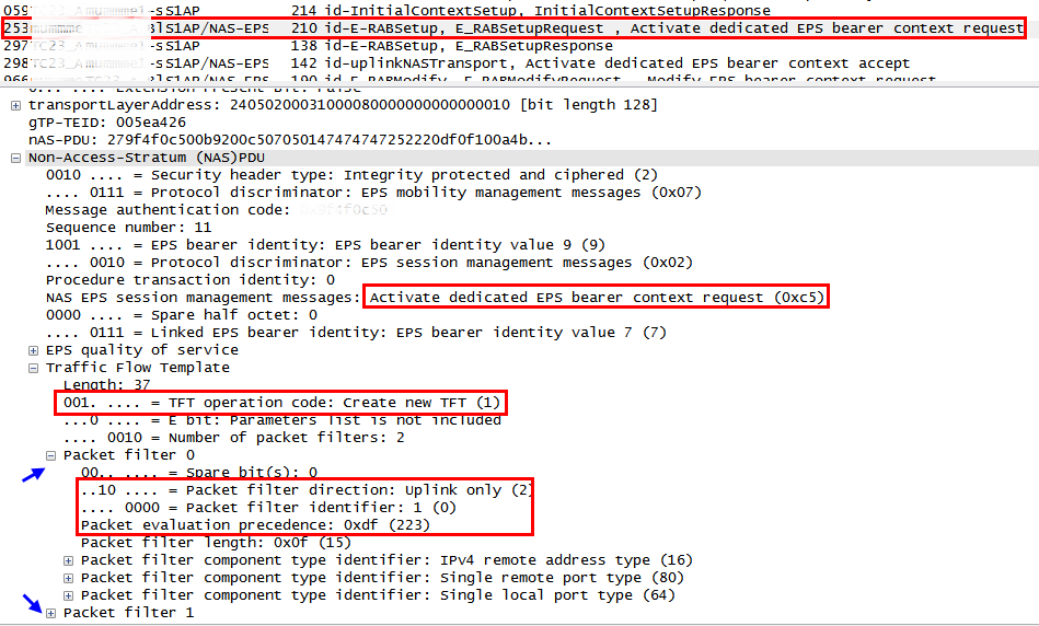
The following snapshot shows the TFT included in the Activate dedicated EPS bearer (MME ->eNB) captured over S1AP. As the TFT is included in the NAS message, it is delivered to the UE transparently so it can be used by the UE.

In a nutshell, the uplink-only TFT is created by the PGW based on the received PCC rules and sent to the UE so the UE can utilize it to filter and map the outgoing IP packets with the corresponding uplink EPS bearer.
II. TFT errors
The TFT is delivered from the MME to UE or vice versa contained in a NAS message over S1AP and the RRC interfaces. The TFT errors indicate operational inconsistencies from semantics or syntax perspectives between TFT operations, packet filters and NAS messages and once detected, it leads to the failure of EPS bearer level operations. The 3GPP TS24.301 has specified four types of TFT related errors as below:
(1) Semantic error in the TFT operation is more likely the case when there is a contextual inconsistency in the TFT operation. The following shows example cases:
- The TFT operation of other than "Create a new TFT" in the Activate dedicated EPS bearer context request.
- The TFT operation of "Delete packet filters from existing TFT" when the deletion will result in the empty TFT.
(2) Syntactical error in TFT operations is more likely the case when there is a logical inconsistency between TFT operation and the packet filters. The following shows example cases:
- The TFT operation of "Create a new TFT" and the empty packet filter list in the TFT IE.
- The TFT operation of "Add packet filters in existing TFT" and the empty packet filter list in the TFT IE.
- The TFT operation of "Delete packet filters from existing TFT" when there is no corresponding packet filter in the existing TFT.
(3) Semantic error(s) in packet filter(s) is more likely the case when a packet filter consists of conflicting packet filter component which would render the packet filter ineffective.
(4) Syntactical error(s) in packet filters(s) is more likely the case when two or more packet filters in the resultant TFT would have component(s) with identical values such as the same packet filter identifiers, the same packet filter precedence values, etc.
Each of the above error cause can appear in the following NAS messages as an ESM cause:
(1) The Activate dedicated EPS bearer context reject (UE-->MME) as a failure to create the dedicated EPS bearer.
(2) The Modify EPS bearer context reject (UE-->MME) as a failure to modify the dedicated EPS bearer.
(3) The Bearer Resource Allocation reject (MME-->UE) as a failure to initiate the activation of the dedicated EPS bearer.
(4) The Bearer Resource Modification reject (MME-->UE) as a failure to initiate the update of the dedicated EPS bearer.
III. Case study
The following snapshot has been captured while testing the conference call scenario. Having been sorted out based on the MME-UE-S1AP-ID, it shows the lifetime of the EPS bearer from when it is created until it is released due to the "semantic error in the TFT operation". In the meantime, there are five times of EPS bearer modifications occurred.
NOTE The MME-UE-S1AP-ID is assigned by the MME to identify the UE over S1AP. In the same way, the eNB also identifies the UE by assigning the ENB-UE-S1AP-ID.

The following snapshot shows the TFT in the Activate dedicated EPS bearer context request. Please note that there are two packet filters, one for the RTP and the other one for the RTCP. The TFT operation has to be "Create a new TFT". The packet filter identifiers are 1 and 2 and the precedence values are 223 and 191, respectively.
NOTE the detail of the second packet filter is not shown in this snapshot.

The following snapshot shows the TFT in the first Modify EPS bearer context request. The TFT operation is "Add packet filters to existing TFT". The packet filter identifiers are 3 and 4 and the packet precedence values are 247 and 239, respectively.
NOTE the detail of the second packet filter is not shown in this snapshot.

All the history of packet filters for the rest of operations can also be analyzed following the same way. The following table shows the resulting analysis of the details for all the packet filters during the lifetime of the EPS bearer.

In this example, the last TFT "Add packet filters to existing TFT" operation which is sent in the Modify EPS bearer context request has the same packet precedence value with the existing packet filter #5. Therefore, the UE responds with the ESM cause = "semantic error in the TFT operation" in the Modify EPS bearer context reject.
NOTE The UE seems to have a glitch sending the wrong ESM cause in this test case. The duplicated packet precedence value will lead to the ESM cause of "Syntactical errors in packet filter(s)" according to the 3GPP TS24.301.
I. TFT filter
Once the bearer binding is completed, that is, the PGW builds mapping relations between EPS bearers and the corresponding PCC rules, the PGW requests the creation of the EPS bearer (i.e., Create Bearer Request) towards the MME in which the set of IP 5-tuples are interpreted as a bearer level Traffic Flow Template (TFT). The TFT can be defined either separately for uplink and downlink or for both uplink and downlink. The TFT for the downlink is used by the network element whereas the TFT for the uplink is used by the UE. The following diagram shows the TFT structure when the TFT operation is add, create or replace [TS24.008].

- TFT operation code : the action to be taken to the TFT and/or packet filter list e.g., create, delete, add, replace, etc.
- Number of packet filters : the number of packet filters. In case the operation code is "Delete existing TFT" or "no operation code", the number of filters will be 0. Otherwise, the maximum number of packet filters is 15.
- Packet filter direction: the direction of the traffic, i.e., uplink only, downlink only, bidirectional
- Packet filter identifier: the unique number to identify the packet filter
- Packet filter evaluation precedence: the precedence for the packet filter among all the packet filters in all TFTs associated with the PDP address.
- Packet filter contents: variable components with variable size such as remote/local IPv4/IPv6 address, protocol identifier, remote/local port, etc.
The following snapshot shows the TFT included in the Create Bearer Request (PGW/SGW->MME) captured over S11. The TFT operation code is to "Create a new TFT" and the direction of the IP flow to which this TFT is applied is an "uplink only" as this TFT is supposed to be used by the UE. The precedence value indicates the priority for this filter among other filters to be applied to the IP flow. Therefore this priority value must be locally unique in the UE. In this example, the IPv4 remote address indicates the P-CSCF address.

The following snapshot shows the TFT included in the Activate dedicated EPS bearer (MME ->eNB) captured over S1AP. As the TFT is included in the NAS message, it is delivered to the UE transparently so it can be used by the UE.

In a nutshell, the uplink-only TFT is created by the PGW based on the received PCC rules and sent to the UE so the UE can utilize it to filter and map the outgoing IP packets with the corresponding uplink EPS bearer.
II. TFT errors
The TFT is delivered from the MME to UE or vice versa contained in a NAS message over S1AP and the RRC interfaces. The TFT errors indicate operational inconsistencies from semantics or syntax perspectives between TFT operations, packet filters and NAS messages and once detected, it leads to the failure of EPS bearer level operations. The 3GPP TS24.301 has specified four types of TFT related errors as below:
(1) Semantic error in the TFT operation is more likely the case when there is a contextual inconsistency in the TFT operation. The following shows example cases:
- The TFT operation of other than "Create a new TFT" in the Activate dedicated EPS bearer context request.
- The TFT operation of "Delete packet filters from existing TFT" when the deletion will result in the empty TFT.
(2) Syntactical error in TFT operations is more likely the case when there is a logical inconsistency between TFT operation and the packet filters. The following shows example cases:
- The TFT operation of "Create a new TFT" and the empty packet filter list in the TFT IE.
- The TFT operation of "Add packet filters in existing TFT" and the empty packet filter list in the TFT IE.
- The TFT operation of "Delete packet filters from existing TFT" when there is no corresponding packet filter in the existing TFT.
(3) Semantic error(s) in packet filter(s) is more likely the case when a packet filter consists of conflicting packet filter component which would render the packet filter ineffective.
(4) Syntactical error(s) in packet filters(s) is more likely the case when two or more packet filters in the resultant TFT would have component(s) with identical values such as the same packet filter identifiers, the same packet filter precedence values, etc.
Each of the above error cause can appear in the following NAS messages as an ESM cause:
(1) The Activate dedicated EPS bearer context reject (UE-->MME) as a failure to create the dedicated EPS bearer.
(2) The Modify EPS bearer context reject (UE-->MME) as a failure to modify the dedicated EPS bearer.
(3) The Bearer Resource Allocation reject (MME-->UE) as a failure to initiate the activation of the dedicated EPS bearer.
(4) The Bearer Resource Modification reject (MME-->UE) as a failure to initiate the update of the dedicated EPS bearer.
III. Case study
The following snapshot has been captured while testing the conference call scenario. Having been sorted out based on the MME-UE-S1AP-ID, it shows the lifetime of the EPS bearer from when it is created until it is released due to the "semantic error in the TFT operation". In the meantime, there are five times of EPS bearer modifications occurred.
NOTE The MME-UE-S1AP-ID is assigned by the MME to identify the UE over S1AP. In the same way, the eNB also identifies the UE by assigning the ENB-UE-S1AP-ID.

The following snapshot shows the TFT in the Activate dedicated EPS bearer context request. Please note that there are two packet filters, one for the RTP and the other one for the RTCP. The TFT operation has to be "Create a new TFT". The packet filter identifiers are 1 and 2 and the precedence values are 223 and 191, respectively.
NOTE the detail of the second packet filter is not shown in this snapshot.
The following snapshot shows the TFT in the first Modify EPS bearer context request. The TFT operation is "Add packet filters to existing TFT". The packet filter identifiers are 3 and 4 and the packet precedence values are 247 and 239, respectively.
NOTE the detail of the second packet filter is not shown in this snapshot.

All the history of packet filters for the rest of operations can also be analyzed following the same way. The following table shows the resulting analysis of the details for all the packet filters during the lifetime of the EPS bearer.

NOTE The UE seems to have a glitch sending the wrong ESM cause in this test case. The duplicated packet precedence value will lead to the ESM cause of "Syntactical errors in packet filter(s)" according to the 3GPP TS24.301.
Red Mouse


